


Section 2
MAJOR GENERATOR COMPONENTS
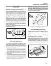
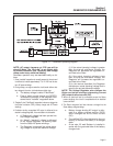
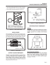
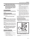
3. Two excitation winding output leads (No. 2 and 6). These leads
deliver unregulated excitation current to the voltage regulator.
4. Three (3) battery charge output leads (No. 55, 66 and 77).
Figure 2-2. – Stator Output Leads
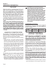
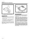
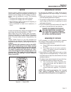
BRUSH HOLDER
The brush holder is retained in the rear bearing carri-
er by two M5 screws. It retains two brushes, which
contact the Rotor slip rings and allow current flow
from stationary parts to the revolving Rotor. The posi-
tive (+) brush is located nearest the Rotor bearing.
Figure 2-3. – Brush Holder
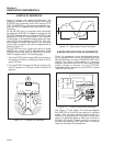
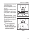
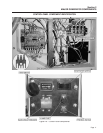
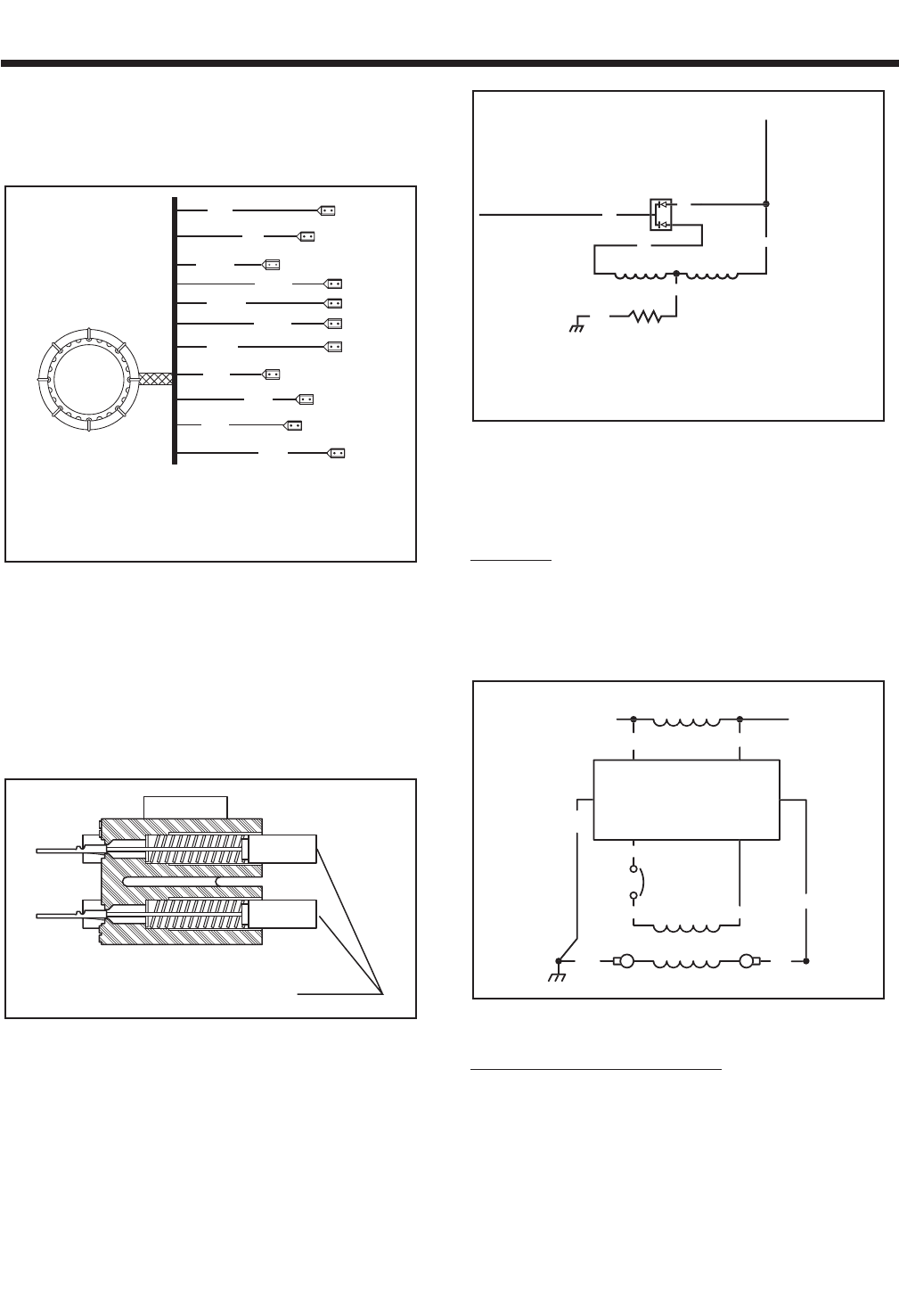
BATTERY CHARGE COMPONENTS
The Stator incorporates dual battery charge windings.
A battery charge rectifier (BCR) changes the AC out-
put of these windings to direct current (DC). Battery
charge winding output is delivered to the unit battery
via the rectifier, a 14 amp fuse and Wire No. 15. A
one ohm, 25 watt resistor is connected in series with
the grounded side of the circuit.
Figure 2-4. – Battery Charge Circuit
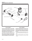
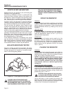
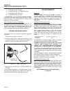
EXCITATION CIRCUIT COMPONENTS
GENERAL:
During operation, the Rotor's magnetic field induces a
voltage and current flow into the Stator excitation
winding. The resultant AC output is delivered to a
voltage regulator via an excitation circuit breaker
(CB2).
Figure 2-5. – Schematic: Excitation Circuit
EXCITATION CIRCUIT BREAKER:
The excitation circuit breaker (CB2) is self-resetting
and cannot be reset manually. Should the breaker
open for any reason, excitation current flow to the
Rotor is lost. The unit’s AC output voltage will then
drop to a value equal to the Rotor's residual magnet-
ism (about 7-12 VAC).
DPE WINDIN
G
V
O
LTA
GE
RE
GU
LAT
OR
P
O
WER WINDIN
G
ELE
C
TR
O
NI
C
0F
FIELD
C
B
2
0K
2
2A
22
S
4
6
4
11
S
BATTERY
C
HAR
G
E WINDIN
G
T
O
BATTERY
T
O
EN
G
IN
E
CO
NTR
O
LLE
R
C
IR
CU
IT B
O
AR
D
0N
R
1
55
1
5
77
B
CR
66
66
B
C
R = Battery Char
g
e Rectifie
r
R1 = One Ohm, 25 Watt Resistor
BRUSHES
2
6
11
11
22
22
33
44
66
55
77
Leads 2 & 6 =Stator Excitation Winding
Leads 11 & 22 = Voltage Sensing Leads
Leads 11 & 22, 33 & 44 = AC Power Windings
Leads 55, 66, 77 = Battery Charge Windings
Page 9