


Section 7
DIAGNOSTIC TESTS
Page 45
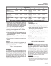
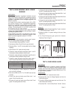
* Resistance values in ohms at 20° C. (68° F.). Actual readings
may vary depending on ambient temperature. A tolerance of
plus or minus 5% is allowed.
RESULTS:
1. For Steps 2 & 3, keep in mind that the resistance values are
very low. Depending upon the quality of the VOM, it may read
“
Continuity” across these windings. Exercise good judgement
with these values.
2. If Steps 2, 3, 4, 5 & 6 fail any test, replace the Stator.
3. In Step 7, if Wire 0 reads “Continuity”, but resistor does not
measure 1 ohm, replace the Battery Charge Resistor.
4. If all of the Steps in this test pass, perform “Insulation
Resistance Test” on page 13.
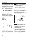
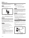
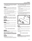
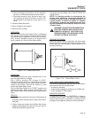
TEST 18 - TRY CRANKING THE ENGINE
DISCUSSION:
If the Pre-Heat Switch on the generator panel is actu-
ated, but the Fuel Pump does not run (priming func-
tion doesn't work), perhaps battery voltage is not
available.
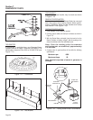
PROCEDURE:
Hold the Start-Stop Switch at “START”. The engine
should crank and start.
RESULTS:
1. If the engine cranks normally, but the pre-heat function still
doesn't work, go to Test 19.
2. If engine will not crank, go to Test 21. Refer to Problem 6 of
Section 6.
3. If engine cranks but won't start, go to Problem 7 of Section 6.
4. If engine starts hard and runs rough, go to Problem 8 of
Section 6.
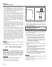
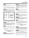
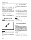
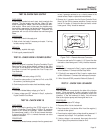
TEST 19- TEST PRE-HEAT SWITCH
DISCUSSION:
A defective pre-heat switch can prevent the pre-heat
function from occurring.
(Also see “Pre-Heat Switch,” page 26).
NOTE: The glow plugs can be damaged by exces-
sive use of the preheat switch. Press the preheat
switch for 30 seconds or less to prevent such
damage.
PROCEDURE:
1. Set a VOM to read battery voltage (12 VDC).
2. Connect the positive (+) meter test lead to the Wire 15 terminal
of the Pre-Heat Switch (leave Wire 15 connected to the
switch). Connect the negative (-) meter test lead to ground.
The meter should indicate battery voltage.
3. Connect the positive (+) meter test lead to the Wire 150 termi-
nal of the Pre-Heat Switch, the negative (-) meter test lead to
frame ground.
a. With the Pre-Heat Switch NOT actuated, no voltage
should be indicated.
b. Actuate the switch to its “PRE-HEAT” position and
the meter should read battery voltage.
4. Set VOM to measure ohms.
5. Connect the positive (+) meter test lead to the Wire 150 termi-
nal of the Pre-Heat Switch (leave Wire 150 connected to the
switch). Connect the negative (-) meter test lead to a clean
frame ground. Continuity should be measured.
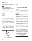
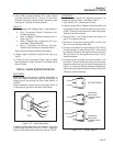
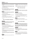
Figure 7-10. – Pre-Heat Switch
RESULTS:
1. If battery voltage is not indicated in Step 2, and the battery and
fuse are both good, Wire 15 will need to be checked for an
open condition.
2. If “Infinity” is measured in Step 5, Wire 150 will need to be
replaced.
3. If battery voltage is not present in Step 3, replace the switch.
4. If battery voltage is present in Step 3, proceed to the next test
in the Flow Chart.
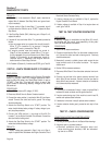
TEST 20- CHECK FUEL PUMP
DISCUSSION:
The fuel pump delivers fuel to the fuel injector pump.
It is powered by Wire 14 when the pre-heat switch is
pressed or when the unit is running. Without fuel to
the engine, combustion will not occur.
150
15
SW
1
50
1
5
1
50
BH1-1
0
A. Pictorial
B. Schematic