


Section 8
ASSEMBLY
MAJOR DISASSEMBLY
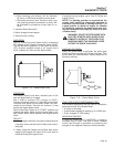
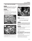
ENCLOSURE/ PANEL REMOVAL:
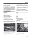
Using a 10-mm socket, remove all screws on all pan-
els except the lower screws on the radiator side
panel. Remove the top panel first, then the side and
rear. When removing the front panel, the main con-
trol panel is mounted onto the front sheet metal.
There are five nuts holding them together that will
need to be removed in order to separate. The wiring
harness connections will need to be disconnected to
completely separate the two pieces.
STATOR/ROTOR/ENGINE REMOVAL:
After the panel assemblies are removed, the tech will
have full access to the components of the unit for
easier removal.
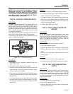
STATOR:
1. Remove the front belt tensioner by using a ¾" socket and
wrench.
2. Loosen bolt and nut and remove.
3. Use a 16-mm socket for the rear tensioner.
4. Remove the rear and front belts.
5. Remove the two screws mounting the electric fuel pump to the
bottom frame by using a 10-mm socket.
6. Disconnect the wiring harness from the fuel pump.
7. Remove air filter and rubber hose from the metal cross mem-
ber frame by using a flat tip screwdriver.
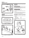
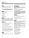
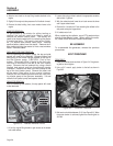
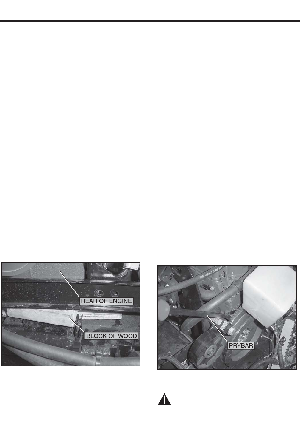
8. Place a block of wood under the rear of the engine for support.
Figure 8-1. – Block of Wood Under Rear of Engine
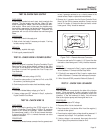
9. Remove the two bolts that mount the rear cross member frame
to the bottom frame through the rubber mount.
10. Remove the four bolts that mount the engine to the cross
member.
11. Remove the two hold down bolts mounting the brush assem-
bly to the rear-bearing carrier.
12. Remove Wire 55 going to the battery charge resistor right
below the stator.
13. Using a 13-mm, remove the four stator hold down bolts. The
bottom two run through the rear cross member frame. With the
bottom two removed, the rear cross member will be able to be
removed.
14. Using a rubber mallet, tap off the rear-bearing carrier.
15. Remove the stator (be careful, not to hit the battery charge
resistor).
ROTOR:
1. Use a prybar to stabilize the rotor pulley and loosen from rotor
bolt.
2. Using a rubber mallet, tap off the rotor pulley.
3. Remove the rotor.
The front bearing carrier is now available for removal
as well.
ENGINE:
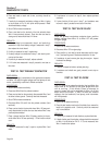
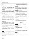
In order for the engine to be removed, the flywheel
will need to be removed first.
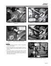
1. Using a prybar, stabilize the flywheel and remove the 6 bolts
mounting the flywheel to the engine.
2. Remove flywheel.
3. Remove rubber fuel lines mounting to the top of the fuel injec-
tor pump.
Figure 8-2. – Using Prybar to Stabilize Flywheel
CAUTION! Fuel is hazardous.
Page 57