


Section 7
DIAGNOSTIC TESTS
Page 39
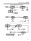
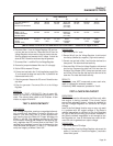
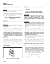
TEST 4 RESULTS
ABCDEFG
VOLTAGE RESULTS ABOVE ABOVE BELOW ZERO OR BELOW BELOW ABOVE
WIRE 2 & 6 60 VAC 60 VAC 60 VAC RESIDUAL 60 VAC 60 VAC 60 VAC
EXCITATION WINDING VOLTAGE
(5-12 VAC)
VOLTAGE RESULTS ABOVE BELOW ABOVE ZERO OR BELOW BELOW ABOVE
WIRE 11 & 22 60 VAC 60 VAC 60 VAC RESIDUAL 60 VAC 60 VAC 60 VAC
POWER WINDING VOLTAGE
SENSE LEADS (5-12 VAC)
ROTOR AMP DRAW .87-.79 A .87-.79 A .87-.79 A ZERO ≥1.2 A .87-.79 A ZERO
QP75D ± 20% ± 20% ± 20% CURRENT ± 20% CURRENT
(MODEL 4270) DRAW DRAW
(MATCH RESULTS WITH LETTER AND REFER TO FLOW CHART – Problem 2 on Pages 30 & 31)
6. Disconnect Wire 11 from the Voltage Regulator (VR) and con-
nect one test lead to that wire. Disconnect Wire 22 from the
Voltage Regulator and connect the other test lead to that wire.
Start the generator and measure the AC voltage. It should be
above 60 VAC. Record the results and stop the generator.
7. Re-connect Wire 11 and Wire 22 to the Voltage Regulator.
8. Remove the jumper wire between Wire 4 and 12 volt supply.
9. Set the VOM to measure DC amps.
10. Connect one test lead to the 12 volt fused battery supply Wire
15, and connect the other test lead to Wire 4 (should still be
disconnected from the VR).
11. Start the generator. Measure the DC current. Record the rotor
amp draw.
12.Stop the generator. Re-connect Wire 4 to the Voltage
Regulator.
RESULTS:
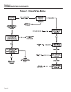
Proceed to “TEST 4 RESULTS” (top of page 40).
Match all results to corresponding column in the
chart. The column letter refers to the Problem 4 flow
charts on pages 28 and 29.
TEST 5- WIRE CONTINUITY
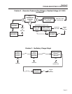
DISCUSSION:
The Voltage Regulator receives unregulated alternat-
ing current from the Stator Excitation Winding via
Wires 2 (162 and CB2), and 6. It also receives volt-
age sensing from the Stator AC Power Windings via
Wires 11 and 22. The regulator rectifies the AC from
the Excitation Winding and, based on the sensing sig-
nals, regulates that DC current flow to the Rotor. The
rectified and regulated current flow is delivered to the
Rotor Brushes via Wires 4 (+) and 0 (-). This test will
verify the integrity of Wires 0 and 162.
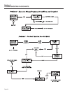
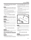
PROCEDURE:
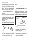
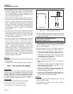
1. Set a VOM to its “Rx1” scale.
2. Remove Wire 0 from the Voltage Regulator, fourth terminal
from the top (identified by a negative (-) sign next to terminal).
3. Connect one test lead to Wire 0 and the other test lead to a
clean ground. The meter should read continuity.
4. Disconnect Wire 162 from the Voltage Regulator, sixth terminal
from the top. Disconnect the other end of this wire from the
Excitation Circuit Breaker (CB2). Connect one test lead to one
end of Wire 162 and the other test lead to the other end of the
same wire. The meter should read continuity.
RESULTS:
If continuity was NOT measured across each wire,
repair or replace the wires as needed.
If continuity WAS measured, proceed to Test 6.
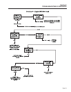
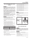
TEST 6- CHECK FIELD BOOST
DISCUSSION:
Field boost current is delivered to the Rotor only while
the engine is being cranked. This current helps
ensure that adequate “pickup” voltage is available to
turn the Voltage Regulator on and build AC output
voltage.
Loss of the field boost function may or may not result
in a problem with AC output voltage. If the Rotor's
residual magnetism is sufficient to turn the Regulator
on, loss of the function may go unnoticed. However, if
the Rotor's residual magnetism is not enough to turn
the Regulator on, loss of field boost can result in fail-
ure of the unit to generate an output voltage.
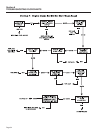
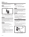
PROCEDURE:
1. Set VOM to measure DC voltage.
2. Disconnect Wire 4 from the Voltage Regulator and connect the
positive (+) test lead to it. Connect the negative (-) test lead to
a clean frame ground.