


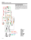
Section 5
ENGINE DC CONTROL SYSTEM
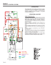
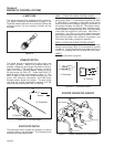
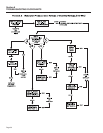
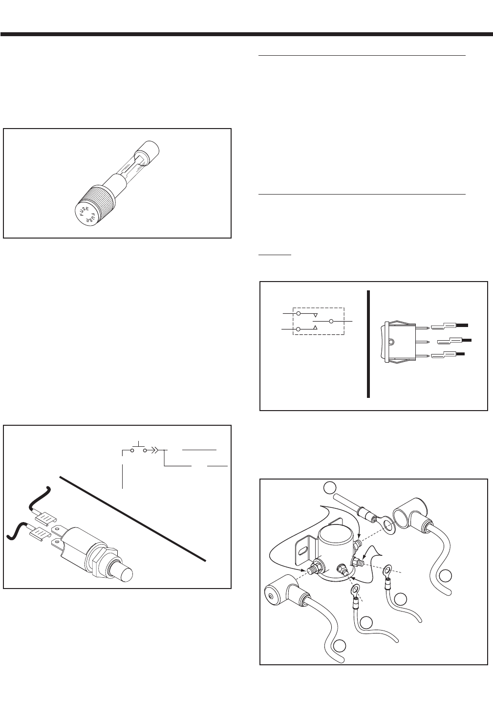
14 AMP FUSE
This panel-mounted Fuse protects the DC control cir-
cuit against overload and possible damage. If the
Fuse has melted open due to an overload, neither the
priming function nor the cranking function will be
available.
Figure5-4
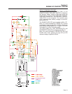
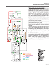
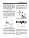
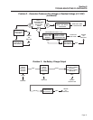
PREHEAT SWITCH
The diesel engine is equipped with glow plugs, one
for each cylinder. When the preheat switch is
pressed, voltage will go through the switch to the pre-
heat contactor. The preheat contactor (normally
open) now closes, allowing battery voltage to go to
the glow plugs via Wire 157. Power from Wire 157
goes through a diode and changes to Wire 14. This
Wire 14 goes to the circuit board powering the fuel
pump, fuel solenoid, hourmeter, and field boost
through another diode and resistor. The glow plugs
now heat the engine combustion chamber, and the
injector pump is primed with fuel for starting.
Figure 5-5. – Pre-heat Switch
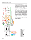
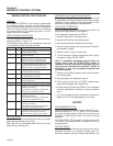
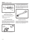
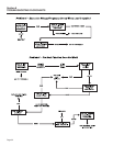
START/STOP SWITCH
The start/stop switch allows the operator to control
cranking, startup, and shutdown. The following wires
connect to the start/stop switch:
WIRE 17 (FROM THE ENGINE CONTROL BOARD):
This is the crank and start circuit. When the switch is
set to start, Wire 17 is connected to ground via Wire
0. With Wire 17 grounded, a crank relay on the circuit
board energizes and battery voltage is delivered to
the starter contactor via Wire 56. The starter contac-
tor energizes and its normally open contacts close
allowing battery voltage through Wire 16 to the starter
motor and the engine will now crank. With Wire 17
grounded, a run relay on the circuit board energizes
and battery voltage is delivered to the Wire 14 circuit.
Now the fuel pump, fuel solenoid, hourmeter, and
field boost has battery voltage for operation.
WIRE 18 (FROM THE ENGINE CONTROL BOARD):
This is the engine stop circuit. When the start/stop
switch is set to stop, Wire 18 is connected to ground
via Wire 0. Circuit board action then opens the circuit
to Wire 14, stopping fuel flow, causing the unit to stop.
WIRE 0:
Connects the switch to ground.
Figure 5-6. – Start/Stop Switch
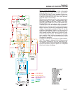
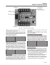
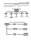
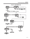
STARTER CONTACTOR & MOTOR
Figure 5-7. – Starter Contactor and Connections
OUTER POSTS
SMALL
LUGS
TO STARTER
TO BATTERY
TO GROUND
TO BOARD
TO FUSE
16
56
0
13
13
17
0
1
8
A. Schematic
B. Pictorial
1
8
S
W
1
17
(
STOP
)
(
START
)
0
150
15
SW
1
50
1
5
1
50
BH1-1
0
A. Pictorial
B. Schematic
Page 26