


Section 7
DIAGNOSTIC TESTS
Page 41
TEST 8- CHECK SENSING LEADS / POWER
WINDINGS
DISCUSSION:
The Voltage Regulator “regulates” excitation current
flow to the Rotor by electronically comparing sensing
voltage to a pre-set reference voltage. The sensing
voltage is delivered to the Voltage Regulator via
Wires 11 and 22.
If an open circuit exists in sensing leads 11S or 22S,
the normal reaction of an unprotected Regulator
would be to increase the excitation current to the
Rotor in an effort to increase the actual AC output
voltage. This would result in a “full field” condition and
an extremely high AC output voltage.
To protect the system against such a high AC output
voltage, the Voltage Regulator will shut down if sens-
ing voltage signals are lost.
If the regulator shuts down, the generator's AC output
voltage will decrease to a value that is equal to the
Rotor's residual magnetism (about 5-12 VAC).
PROCEDURE:
Gain access to the generator control panel interior.
Test the Stator power windings, as follows:
1. From main breaker, disconnect Wires 11 and 44.
2. Also disconnect Wires 22 and 33 from the ground terminal.
3. Disconnect Wires 11 and 22 ( sensing leads) from the Voltage
Regulator.
4. Set a VOM to its “Rx1” scale and zero the meter.
5. Connect the meter test leads across Stator leads 11 and 22.
Normal power winding resistance should be read.
6. Connect the meter test leads across Stator leads 33 and 44.
Normal power winding resistance should be read.
7. Connect the meter test leads across Stator sensing leads 11
and 22. Normal Power Winding resistance should be read.
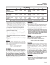
AC POWER WINDING RESISTANCE * QP75D
ACROSS WIRES: OHMS
11 & 22
0.159W
33 & 44 0.184W
* Resistance values in ohms at 20° C. (68° F.). Actual readings
may vary depending on ambient temperature. A tolerance of
plus or minus 5% is allowed.
8. Now, set the VOM to its “Rx1 K” or “Rx10,000” scale and zero
the meter.
9. Connect the meter test leads across Stator lead 11 and
ground. “Infinity” should be read.
10. Connect the meter test leads across Stator lead 33 and
ground. The reading should be “Infinity”.
11. Connect the meter test leads across Stator leads Wire 11 and
Wire 33. The reading should be “Infinity”.
12. Connect the meter test leads across Stator leads Wire 11 and
Wire 66. The reading should be “Infinity”.
13. Connect the meter test leads across Stator leads Wire 33 and
Wire 66. The reading should be “Infinity”.
14. Connect the meter test leads across Stator leads Wire 11 and
Wire 2. The reading should be “Infinity”.
15. Connect the meter test leads across Stator leads Wire 33 and
Wire 2. The reading should be “Infinity”.
RESULTS:
1. If the Stator passes all steps except Step 7, repair, re-connect
or replace Sensing leads 11 and 22.
2. Replace the Stator if it’s power windings fail the test. (Note
Result No. 1).
3. If the Power Windings test good, perform the “Insulation
Resistance Test” on Page 13.
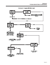
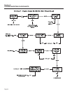
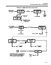
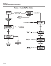
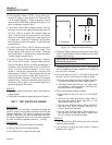
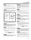
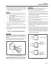
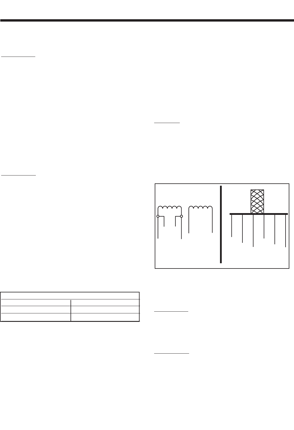
Figure 7-5. – Stator Power Winding Leads
TEST 9- CHECK BRUSH LEADS
DISCUSSION:
In Test 4, if application of battery voltage to the Rotor
did NOT result in an output of about one-half rated
voltage, the brush leads could be one possible cause
of the problem. This test will check Wires 4 and 1 for
an open circuit condition.
PROCEDURE:
1. Set a VOM to its “Rx1” scale and zero the meter.
2. Disconnect Wire 4 from the Voltage Regulator and from the
Rotor brush terminal.
3. Connect the VOM test leads across each end of the wire. The
meter should read “Continuity”.
4. Disconnect Wire 1 from the Rotor Brush Terminal. Connect
A.
S
chemati
c
B. Pictoria
l
33
33
44
44
11
11
11
22
11
22
22
22