


Section 7
DIAGNOSTIC TESTS
b.Open armature (wire broken) will be indicated
by low or no RPM and excessive current draw.
c.Grounded armature (wire insulation worn and
wire touching armature lamination or shaft). Will
be indicated by excessive current draw or no
RPM.
3. A defective Starter Motor switch.
4. Broken, damaged or weak magnets.
5. Starter drive dirty or binding.
DISCUSSION:
Test 25 verified that circuit board action is delivering
DC voltage to the Starter Contactor Relay (SCR).
Test 26 verified the operation of the Starter Contactor
(SC). Another possible cause of an "engine won't
crank" problem is a failure of the Starter Motor.
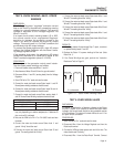
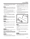
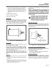
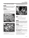
Figure 7-14. – Starter Motor (SM)
PROCEDURE:
The battery should have been checked prior to this
test and should be fully charged.
Set a VOM to measure DC voltage (12 VDC).
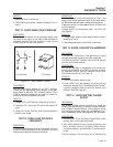
Connect the meter positive (+) test lead to the Starter
Contactor stud which has the small jumper wire con-
nected to the Starter. Connect the common (-) test
lead to the Starter Motor frame.
Set the Start-Stop Switch to its "START" position and
observe the meter. Meter should indicate battery volt-
age, Starter Motor should operate and engine should
crank.
RESULTS:
1. If battery voltage is indicated on the meter but Starter Motor did
not operate, remove and bench test the Starter Motor (see fol-
lowing test).
2. If battery voltage was indicated and the Starter Motor tried to
engage (pinion engaged), but engine did not crank, check for
mechanical binding of the engine or rotor.
If engine turns over slightly, go to Test 35 “Check and
Adjust Valves.”
NOTE: If a starting problem is encountered, the
engine itself should be thoroughly checked to
eliminate it as the cause of starting difficulty. It is
a good practice to check the engine for freedom
of rotation by removing the spark plugs and turn-
ing the crankshaft over slowly by hand, to be sure
it rotates freely.
WARNING!: DO NOT ROTATE ENGINE WITH
ELECTRIC STARTER WITH SPARK PLUGS
REMOVED. ARCING AT THE SPARK PLUG
ENDS MAY IGNITE THE GASOLINE VAPOR
EXITING THE SPARK PLUG HOLE.
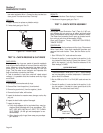
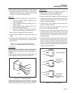
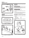
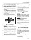
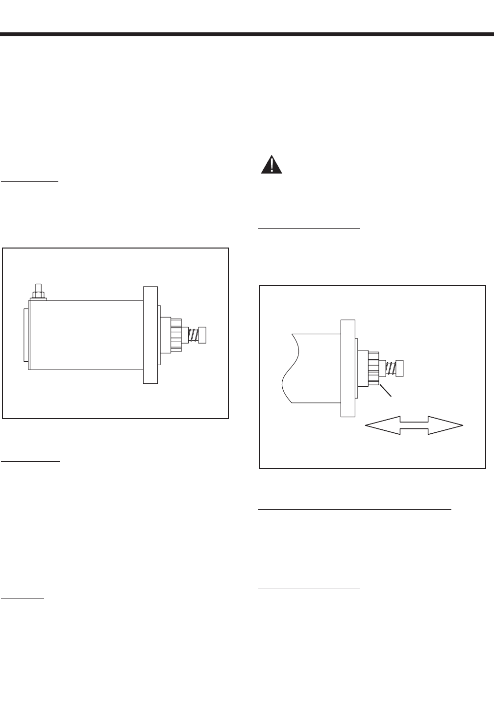
CHECKING THE PINION:
When the Starter Motor is activated, the pinion gear
should move and engage the flywheel ring gear. If the
pinion does not move normally, inspect the pinion for
binding or sticking.
Figure 7-15. – Check Starter Pinion
TOOLS FOR STARTER PERFORMANCE TEST:
The following equipment may be used to complete a
performance test of the Starter Motor:
• A clamp-on ammeter.
• A tachometer capable of reading up to 10,000 rpm.
• A fully charged 12 VDC battery.
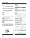
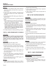
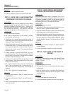
MEASURING CURRENT:
To read the current flow, in AMPERES, a clamp-on
ammeter may be used. This type of meter indicates
current flow through a conductor by measuring the
strength of the magnetic field around that conductor.
PINION
Page 49