


approximately 0.8 Amps. Apply full load to the generator. The
amp reading should increase to approximately 2 Amps.
RESULTS:
1. If amperage was measured between 0.8 to 2 Amps in Step 2
and Step 3, the charging system is working.
2. If no amperage was measured, check the VOM fuses and veri-
fy the functioning of the Amp Meter. If DC Amp Meter is good
and no current is measured, go to Test 16
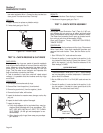
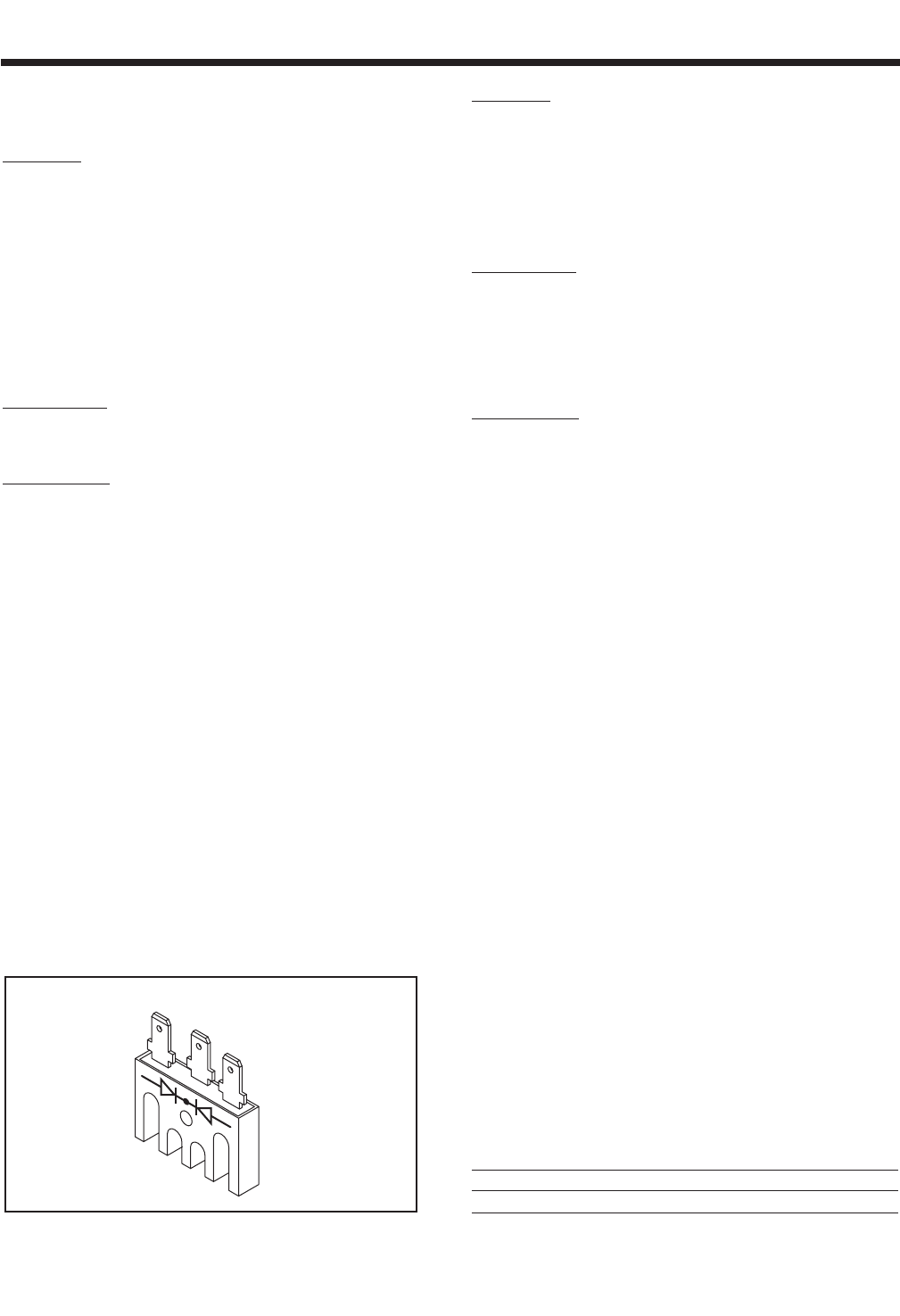
TEST 16 - CHECK BATTERY CHARGE
RECTIFIER
DISCUSSION:
The Battery Charge Rectifier (BCR) is a full wave
rectifier.
PROCEDURE:
1. Disconnect Wire 66, Wire 15 and Wire 77 from the Battery
Charge Rectifier.
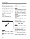
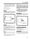
2. Set the VOM to the Diode Test range. Connect the negative (-)
test lead to the center terminal of the BCR. Connect the posi-
tive (+) test lead to an outer terminal. The meter should mea-
sure approximately 0.47 to 0.5 volts.
3. Connect the positive (+) test lead to the center terminal of the
BCR. Connect the negative (-) test lead to to an outer terminal.
The meter should measure “Infinity.” Connect the negative test
lead to the other outer terminal. “Infinity” should once again be
measured.
Short to Ground:
4. Set the VOM to measure resistance. Connect the positive (+)
test lead to the case housing of the BCR. Connect the negative
(-) test lead to an outer terminal. “Infinity” should be measured.
Now connect the negative test lead to the BCR center terminal.
“Infinity” should be measured. Next, connect the negative test
lead to the remaining outer BCR terminal. Once again “Infinity”
should be measured.
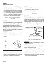
Figure 7-9. – Battery Charge Rectifier
RESULTS:
1. If any of the previous steps has failed, replace the Battery
Charge Rectifier.
TEST 17 - CHECK BATTERY CHARGE
WINDINGS / BATTERY CHARGE RESISTOR
DISCUSSION:
The Battery Charge Winding (BCW) produces AC
voltage that is delivered to the Battery Charge
Rectifier. The Battery Charge Winding is a center
tapped winding consisting of the following Stator
Leads: Wire 66, Wire 77 and Wire 55. The Battery
Charge Resistor is used as a current limiting resistor.
PROCEDURE:
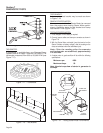
1. Disconnect the Stator Leads (Wire 66 and Wire 77) from the
Battery Charge Rectifier. (Be sure to disconnect Stator Lead
Wire 66 “Black” from Wire 66 “Blue” connector for this test).
Disconnect the Stator Lead Wire 55 from the Battery Charge
Resistor.
2. Set the VOM to measure resistance at the “R x 1” scale.
Connect one test lead to Stator Lead Wire 66. Connect the
other test lead to Stator Lead Wire 55. Normal Battery Charge
Winding resistance should be measured.
3. Connect one test lead to Stator Lead Wire 77. Connect the
other test lead to Stator Lead Wire 55. Normal Battery Charge
Winding resistance should be measured.
4. Connect one test lead to Stator Lead Wire 55. Connect the
other test lead to Stator Leads Wire 11 & 33 at the back of
CB1. “Infinity” should be measured.
5. Connect one test lead to Stator Lead Wire 55. Disconnect
Stator Lead Wire 2 from the DPE circuit breaker (CB2) and
connect the other test lead to Wire 2. “Infinity” should be mea-
sured.
6 Connect one test lead to Stator Lead Wire 55. Connect the
other test lead to frame ground. “Infinity” should be measured.
7. Connect one test lead to the Battery Charge Resistor terminal
that Wire 55 was removed from. Connect the other test lead to
frame ground. One (1) ohm should be measured. If 1 ohm was
not measured, remove Wire 0 from the Battery Charge Resistor.
Connect one test lead to Wire 0 and the other test lead to frame
ground. “Continuity” should be measured. Repair or replace
Wire 0 if defective and retest the Battery Charge Resistor.
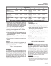
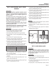
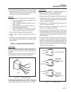
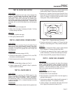
BATTERY CHARGE WINDING RESISTANCE *
QP75D (Model 4270)
ACROSS WIRES: OHMS
55 & 66 0.7Ω
55 & 77 0.5Ω
66
15
77
Section 7
DIAGNOSTIC TESTS
Page 44