


Section 2
MAJOR GENERATOR COMPONENTS
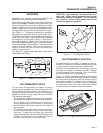
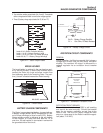
ROTOR ASSEMBLY
The Rotor is sometimes called the “revolving field”,
since it provides the magnetic field that induces a
voltage into the stationary Stator windings. Slip rings
on the Rotor shaft allow excitation current from the
voltage regulator to be delivered to the Rotor wind-
ings. The Rotor is driven by the engine at a constant
speed through a pulley and belt arrangement.
The QUIETPACT 75D utilizes a 2-pole Rotor. This
type of Rotor must be driven at 3600 rpm for a 60-
Hertz AC output, or at 3000 rpm for a 50-Hertz output.
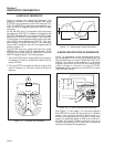
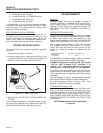
Slip rings should be cleaned. If dull or tarnished,
clean them with fine sandpaper (a 400 grit wet sand-
paper is recommended). DO NOT USE ANY METAL-
LIC GRIT OR ABRASIVE TO CLEAN SLIP RINGS.
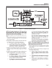
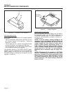
STATOR ASSEMBLY
The Stator is assembled between the front and rear
bearing carriers and retained in that position by four
Stator studs. Windings included in the Stator assem-
bly are (a) dual AC power windings, (b) an excitation
or DPE winding, and (c) a battery charge winding. A
total of eleven (11) leads are brought out of the Stator
as follows:
1. Four (4) Stator power winding output leads (Wires No. 11, 22,
33 and 44). These leads deliver power to connected electrical
loads.
2. Stator Power winding “sensing” leads (11 and 22). These leads
deliver an “actual voltage signal to the electronic Voltage
Regulator.
Page 8
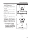
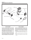
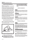
Figure 2-1. Exploded View of Generator
BRUSH HOLDER
STATO R
ROTOR
ENGINE
FLYWHEEL/PULLEY
PULLEY
TENSIONER
BELT
BEARING
BEARING CARRIER
BEARING
CARRIER
BEARING