


Section 7
DIAGNOSTIC TESTS
RESULTS:
1. If “Continuity” is not measured in Step 2, repair, reconnect or
replace Wire 0 (between Start-Stop Switch and ground termi-
nal) as necessary.
2. If engine cranks in Step 3 when Wire 17 is grounded, but will
not crank when the Switch is set to “START”, replace the Start-
Stop Switch.
3. If the Start-Stop Switch (SW1) failed any part of Steps 5 or 6,
replace the switch.
4. If engine will not crank when Wire 17 is grounded, proceed as
follows:
a.Use a jumper wire to connect the circuit board's
Wire 17 (Pin Location 3) to ground. If engine
does NOT crank, proceed to Test 25.
b.If engine cranks now, but would not crank in
Step 3 of the procedure, check Wire 17 for con-
tinuity between the circuit board and Start-Stop
Switch. If “Continuity” is not measured, repair or
replace Wire 17 between the engine control
board and the Start-Stop Switch.
5. For Problem 9 (Section 6), if switch tests GOOD, go to Test 30.
TEST 25 - CHECK POWER SUPPLY TO WIRE 56
DISCUSSION:
If battery voltage is available to the Engine Controller
board in Test 23, then DC voltage should be deliv-
ered to Wire 56 when the Start-Stop Switch is set to
“START” (Test 24). This test will check to see if the
circuit board is delivering battery voltage to the Wire
56 terminal.
PROCEDURE:
1. Set a VOM to measure DC voltage (12 VDC).
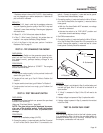
2. Disconnect Wire 56 from its Starter Contactor terminal.
3. Connect the meter positive (+) test lead to Wire 56, just discon-
nected. Connect the other test lead to ground. No voltage
should be indicated.
4. Actuate the Start-Stop Switch to its “START” position. The
meter should indicate battery voltage. If battery voltage is pre-
sent, stop the procedure.
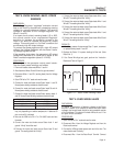
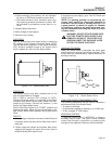
5. Connect the VOM positive (+) test lead to Wire 56 (Pin
Location 7) at the Engine Controller Circuit Board. Connect the
other test lead to frame ground.
6. Actuate the Start-Stop Switch to the “START” position. The
meter should indicate battery voltage.
RESULTS:
1. If battery voltage was measured in Step 6, but not in Step 4,
repair or replace Wire 56 between the Engine Controller Circuit
Board and Starter Contactor Relay.
2. If battery voltage was not available in Step 6, replace the
Engine Controller Circuit Board.
3. If battery voltage is available in Step 4 but engine does not
crank, go to Test 26.
TEST 26- TEST STARTER CONTACTOR
DISCUSSION:
If battery voltage is available to the Wire 56 circuit,
but engine will not crank, one possibility of the prob-
lem is a failed starter contactor.
PROCEDURE:
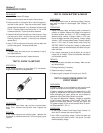
1. Set a VOM to measure resistance.
2. Connect one test lead to Wire 0 on the starter contactor termi-
nal. Connect the other test lead to frame ground. Continuity
should be measured.
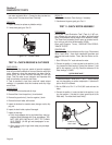
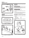
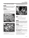
3. Momentarily connect a suitable jumper cable across the two
large terminal studs of the starter contactor. The engine
should crank.
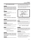
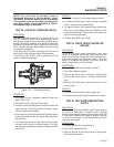
4. Set the VOM to measure resistance.
5. Disconnect Wire 56 and 0 from the starter contactor from termi-
nals.
6. Connect one test lead to the starter contactor terminal from
which Wire 56 was removed. Connect the other test lead to
where Wire 0 was removed. A starter contactor coil resistance
of 4.6 ohms should be measured.
RESULTS:
1. If continuity is not measured in step 1, repair or replace Wire 0
between the starter contactor and the ground terminal.
2. If engine cranks during step 3, but would not crank in test 25,
remove and replace starter contactor.
3. If resistance is incorrect in step 6, replace starter contactor.
4. If starter contactor checks good, proceed to next step in flow-
chart.
TEST 27 - CHECK STARTER MOTOR
CONDITIONS AFFECTING STARTER MOTOR
PERFORMANCE:
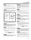
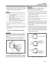
1. A binding or seizing condition in the Starter Motor bearings.
2. A shorted, open or grounded armature.
a.Shorted, armature (wire insulation worn and
wires touching one another). Will be indicated
by low or no RPM.
Page 48