


Section 7
DIAGNOSTIC TESTS
TEST 28- CHECK FUEL SUPPLY
DISCUSSION:
If the engine cranks but won't start, don't overlook the
obvious. The fuel supply may be low. Many RV gen-
erator installations "share" the fuel tank with the vehi-
cles engine. When such is the case, the installer may
have used a generator fuel pickup tube that is shorter
than the vehicle engines pickup tube. Therefore, the
generator will run out of fuel before the vehicle engine
does.
PROCEDURE:
1. Check the fuel level in the supply tank.
2. Attach a fresh fuel supply if necessary and restart. Fuel may
be stale, causing a hard start.
RESULTS:
1. If necessary, replenish fuel supply.
2. If fuel is good, proceed to test 29.
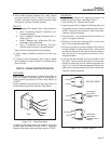
TEST 29 - CHECK WIRE 14 POWER SUPPLY
DISCUSSION:
When the engine is cranked, Engine Controller Circuit
Board action must deliver battery voltage to the Wire
14 circuit, or the engine will not start. This is because
the Wire 14 circuit will operate the Fuel Pump and
Fuel Solenoid.
PROCEDURE:
1. Set a VOM to read battery voltage (12 VDC).
2. Connect the meter positive (+) test lead to Pin 9 on the PCB,
the common (-) test lead to ground.
3. Crank the engine and the meter should read battery voltage.
RESULTS:
1. If the meter indicated battery voltage, go to Test 19.
2. If battery voltage was NOT indicated in Step 3, replace the
Engine Controller Circuit Board.
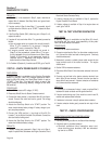
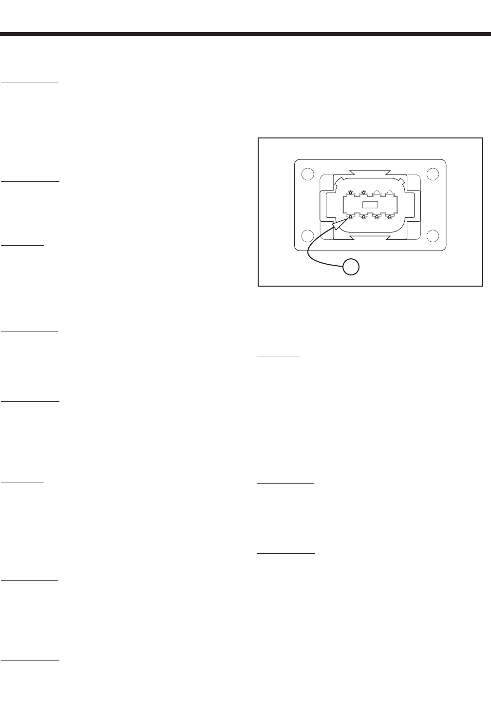
TEST 30 - CHECK WIRE 18
DISCUSSION:
Wire 18 controls sending the STOP signal to the
Engine Controller Circuit Board. If Wire 18 contacts
ground it will initiate a shutdown. Coach manufactur-
ers sometimes install a 15 to 30 foot remote harness.
A ground on Wire 18 in a remote harness can also
cause a shutdown.
PROCEDURE:
1. Remove the remote harness connector from the generator and
re-test. If generator continues to run, a short is present in the
remote harness. Repair or replace the remote harness.
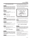
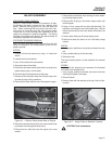
2. Remove the J1 connector from the Engine Controller Circuit
Board. Set the VOM to measure resistance. Connect one test
lead to Pin Location 4. Connect the other test lead to a clean
frame ground. “Infinity” should be measured.
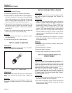
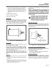
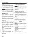
Figure 7-20. – Remote Harness Connector
3. Connect one test lead to Pin Location J1-15. Connect the other
test lead to a clean frame ground. “Infinity” should be measured.
RESULTS:
1. If “Continuity” is measured in Step 2, repair or replace shorted
Wire 18 between J1 Connector and Start-Stop Switch.
2. If “Continuity” was measured in Step 3, repair or replace short-
ed Wire 18 between J1 Connector and remote panel connector.
3. If Wire 18 checks GOOD, proceed to Problem 8 (Section 6).
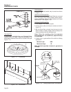
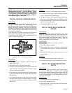
TEST 31 - CHECK FUEL SOLENOID
DISCUSSION:
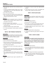
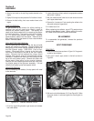
The fuel solenoid is mounted to the side of the injector
pump. Once energized, it pulls a plunger in from the
fuel injector pump and fuel will be allowed to flow to the
injectors. If the fuel solenoid is faulty, fuel will never
flow to the injector pump and the engine won't run.
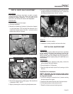
PROCEDURE:
1. Set a VOM to measure D/C voltage.
2. Disconnect Wire 14 to the fuel solenoid.
3. Place the positive (+) test lead on Wire 14 and the negative (-)
test lead on clean ground.
4. Press the prime switch, battery voltage should be measured. If
measured, skip to Step 8. If not, proceed to next Step.
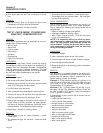
5. If battery voltage is not measured, disconnect other end of
Wire 14 going to the printed circuit board on Pin 9.
4 3 2 1
5 6
18
Page 51