


Page 84
iQ Series, Ultrasonic Generator/Power Supply LS User’s Manual
Dukane Manual Part No. 403-574-01
Automation Thruster Control
Module
Part Number - 110- 4206
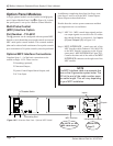
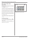
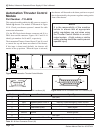
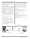
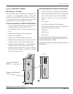
This optional module enables the iQ system to control a
Dukane iQ thruster. The module is illustrated in Figure
10-14. Check your thruster operator’s manual for cable
connection information.
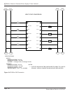
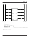
J5 is the HD-26 pin basic thruster connector and J6 is a
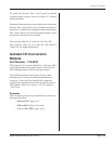
DB-9 abort switch connector. Figures 10-15 and 10-16
identify pin numbers for J6 and J5, respectively.
The Automation Thruster Control Input (J2 pin 9) is used
to control the up and down movement of the thruster.
If this input is deactivated (default), the thruster will
remain in the up position. When the input is activated,
NOTE
It is the responsibility of the machine
builder to ensure that all appropriate
safety regulations are met when using
the Thruster Control Module in an auto-
mated system. A light curtain or similar
safety guarding should be used to prevent
operator injury.
Figure 10-14 Automation Thruster Control Module
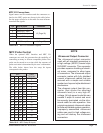
Pin No. Input/Output Function Signal Types
1 Not Used
2 Not Used
3 Input Hardware Abort Power In Normally closed emergency switch contact
4 Input Software Abort Normally open dry contact switch closure to ground
5 Press Inhibit (Gnd) Safety signal
6 Not Used
7 Ground Ground Internal ground
8 Not Used
9 Output Hardware Abort Power Out Normally closed emergency switch contact
Table 10 - V Abort Connector Pinout (J6)
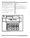
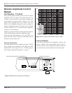
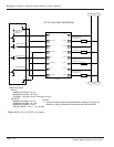
LINE VOLTAGE:
200-240 Vac
50/60Hz, 10A
PE
BASIC THRUSTER
U/S
I
0
J2
J1
J4
J3
ABORT
J5
J6
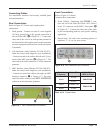
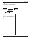
Figure 10-15 DB-9 Connector with Pin Locations (J6)
Figure 10-16 HD-26 Connector with Pin Locations (J5)
1
5
6
9
1
9
10
19
26
18
the thruster will descend to the down position at a speed
that is determined by the pressure regulator setting on the
front of the thruster.