


Page 27Page 26
iQ Series, Ultrasonic Generator/Power Supply LS User’s Manual
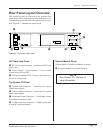
Section 4 – Standard Connections
Page 27Page 26
iQ Series, Ultrasonic Generator/Power Supply LS User’s Manual
Section 4 – Standard Connections
Dukane Manual Part No. 403-574-01
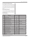
Pin 5 (Remote Setup Selection Bit 2 Input)
Pin 5 is the Remote Setup Selection Bit 2, which is the
third least signicant bit used to select different weld-
ing setups with an automation control system. This input
is also used to select different channels when a Multiple
Probe Controller (MPC) Interface option board is in-
stalled.
Pin 6 (Remote Setup Selection Bit 3 Input)
Pin 6 is the Remote Setup Selection Bit 3, which is the
second most signicant bit used to select different weld-
ing setups with an automation control system. This input
is also used to select different channels when a Multiple
Probe Controller (MPC) Interface option board is in-
stalled.
Pin 7 (Remote Setup Selection Bit 4 Input)
(Not used on the basic model generator)
Pin 7 is the Remote Setup Selection Bit 4, which is
the most signicant bit used to select different welding
setups and can only be used with an advanced control
system. This bit will not be used when a Multiple Probe
Controller (MPC) Interface option board is installed.
Pin 8 (Ultrasound Activation/ Cycle Start
Input)
Pin 8 is used to activate the generator ultrasound output.
Activation of this control input will switch the ultrasound
output ON, and deactivating this signal will switch
ultrasound OFF. This input signal will also function as
a cycle start input, where the ultrasound activation and
timing are completely under the control of the process
controller. Depending on the welding process controller
setup, this input signal could be activated momentarily
to start a welding cycle. See Section 6 for more
information.
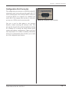
Pin 9 (Automation Thruster Control Input)
Pin 9 is used only when an optional automation thruster
control board is installed. (See Page 76.) Activation of
this input would cause the thruster attached to the option
board to go to the down position. When this signal
deactivates, the thruster will move to the up position. This
option is typically used for a continuous welding process,
when the user wants to retract the ultrasonic stack away
from the process (or material) when the ultrasound is off
or some changes in the process are being made.
Pin 10 (Front Panel Control Lock Input)
Pin 10 is used to lock the front panel user interface,
so an operator cannot change any welding setups or
conguration parameters that are stored in memory.
The user can use the interface controls to view welding
information, but no setup changes are allowed.
Deactivation of this signal allows normal operation,
without any lockout restrictions.
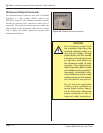
Pin 11 (Press Inhibit for Hand Probes)
Pin 11 is used to disconnect power applied to a press
or thruster, if a hand probe is connected to the system
input connector, for safety considerations. The hand
probe activation switch could unexpectedly start a
welding cycle that activates a press or thruster to the
down position. The hand probe cable connector is wired
to apply chassis ground to this pin, when it is attached
to the system, which activates a press inhibit relay that
disconnects power from the pneumatic press valves. This
pin must be left open whenever a press control board
is installed. Connecting this pin to chassis ground will
inhibit press operation.
Pin 12 (System Latch Reset Input)
Pin 12 is used to reset the Any Fault or System Overload
status outputs (See Status Output descriptions.). If a fault
occurs during a weld cycle, these outputs will normally
remain active until the next weld cycle is initiated.
Activating this input will reset the status output faults
and may simplify automation programming.
Pin 13 (Isolated Common)
Pin 13 is electrically isolated from chassis ground. Using
isolated sourcing (PNP) output drivers, this common line
would be connected to isolated ground potential. Using
isolated sinking (NPN) output drivers, this common line
would be connected to the isolated positive supply voltage
output.
Pin 14 (Not Used)
Pin 14 is an open connection.
Pin 15 (Automation Cycle Stop Input)
Pin 15 is an input control signal that when enabled, can
be used by the automation control system as a redundant
signal to shut the ultrasound output off. This signal could
also be recongured through menu selections to function
as an automation end-of-weld control signal input.