


Page 64
iQ Series, Ultrasonic Generator/Power Supply LS User’s Manual
Dukane Manual Part No. 403-574-01
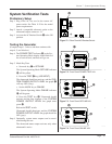
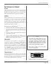
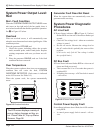
System Power Output Level:
Red
Red - Fault Condition
When the SYSTEM POWER OUTPUT LEVEL turns
red (arrow on the right end of the bar graph), there is
an overload condition that disables generator operation.
See J in Figure 8-2 below.
Overload
When an overload occurs, it will automatically reset
when the next ultrasound activation signal begins. If the
condition persists:
Place the generator OFFLINE and:
1. Check the system: including cables, the acoustic
stack, mounted probe, and/or hand probe. Replace
existing components with ones you know are reli-
able.
2. Place the generator ONLINE, and see if the fault
condition has been corrected.
Over Temperature
When the system overheats, there is an over temperature
condition that will cause the fault, SYSTEM
OVERTEMP DETECTED. (Fault status is indicated
on the LCD screen. See Table 8-I.)
When the system cools, the system automatically
resets.
Generator Fault Does Not Reset
When the system does not automatically reset, the
generator needs servicing.
System Power Diagnostic
Procedures
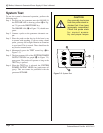
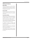
AC Line Fault
If Power Status indicator (B in Figure 8-3 below)
ashes RED at a fast rate of about four ashes per
second:
• Check AC line voltage level – either an over/under
voltage is sensed.
• Do not call service. Measure the voltage level at
the AC outlet which is probably the source of the
problem.
(Call service only if the AC line voltage is within
the specied limits.)
DC Bus Fault
If Power Status indicator ashes RED at a slow rate of
about one ash per second:
• This is normal for 10 to 15 seconds after power is
switched ON.
• If ashing does not stop – a DC bus fault is sensed
– call service.
LOAD
8060 100
OVER
400 20
SYSTEM POWER OUTPUT LEVEL
SYSTEM OPERATING MODE
ON
LINE
OFF
LINE
POWER
TEST
# 1 PART COUNT 125
WELD TIME 0.080 S
POWER 1050 W
ENERGY 350 J
# 1 PART COUNT 125
WELD TIME 0.080 S
POWER 1050 W
ENERGY 350 J
C
A
N
C
E
L
E
N
T
E
R
LOAD
8060 100
OVER
400 20
SYSTEM POWER OUTPUT LEVEL
SYSTEM OPERATING MODE
POWER
TEST
I
N
F
O
O
N
/
O
F
F
L
I
N
E
T
E
S
T
Control Power Supply Fault
Power Status indicator doesn’t ash, but is ON continu-
ously RED:
• A control power supply fault is sensed – call ser-
vice.
Figure 8 - 2 Overload Indication
LOAD
8060 100
OVER
400 20
SYSTEM POWER OUTPUT LEVEL
SYSTEM OPERATING MODE
LOAD
8060 100
OVER
400 20
SYSTEM POWER OUTPUT LEVEL
SYSTEM OPERATING MODE
ON
LINE
OFF
LINE
POWER
TEST
# 1 PART COUNT 125
WELD TIME 0.080 S
POWER 1050 W
ENERGY 350 J
ON
LINE
# 1 PART COUNT 125
WELD TIME 0.080 S
POWER 1050 W
ENERGY 350 J
I
N
F
O
O
N
/
O
F
F
L
I
N
E
T
E
S
T
C
A
N
C
E
L
E
N
T
E
R
J
Figure 8 - 3 Power Status Indicator
B
NOTE
The LCD screen displays a variety of
pop-up status changes as they oc-
cur. Check Table 8-I, Pop-up Status
Screens, Page 58.