


Page 31Page 30
iQ Series, Ultrasonic Generator/Power Supply LS User’s Manual
Section 4 – Standard Connections
Dukane Manual Part No. 403-574-01
Page 31Page 30
iQ Series, Ultrasonic Generator/Power Supply LS User’s Manual
Section 4 – Standard Connections
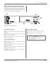
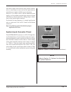
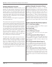
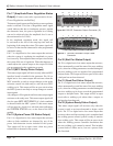
Figure 4 - 6 DB-25F, Generator Output Connector (J3)
Pin 17 (Amplitude/Power Regulation Status
Output) (Contact your sales representative about
Power Regulation availability.)
This status signal is most useful when the power regulation
mode is selected. This Out of Regulation status signal
would indicate that due to inadequate pressure against
the ultrasonic horn, the power regulation level setting
can not be achieved when the amplitude level is set to
the maximum level of 100%.
In the amplitude regulation mode, this signal will
be activated at the end of the ramp-up time until the
beginning of the ramp-down time. This status signal will
be active for the time the ultrasound is at the programmed
amplitude setting.
Pin 17 is a digital active low status output that activates
when the system is regulating the amplitude or power
level correctly. This output becomes an open circuit when
the system falls out of regulation. When that happens, it
cannot adjust the system output to the output level that
was programmed as the regulation set point.
Pin 18 (MPC Ready Status Output)
This status output signal will activate only when an MPC
interface board is installed in the generator. Pin 18 is a
digital active low status output that activates when the
MPC controller is ready to accept changes on the probe
selection control bits and ready to start the next MPC
welding cycle. This output will be an open circuit when
the MPC system is not ready to accept changes to control
input signals.
Any changes will be ignored until this status output signal
activates to the ready state. This status output signal will
also be open (MPC NOT READY) if a fault condition
is detected inside the MPC system. If this status output
will not activate, check for a red fault status indication,
the SYSTEM STATUS LED, on the front of the MPC
module.
Pin 19 (System Power OK Status Output)
Pin 19 is a digital active low status output that activates
when no fault conditions are detected by any of the
power fault detection circuits included in the system.
This output will be an open circuit when any power
related fault is detected in the system.
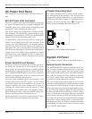
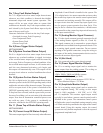
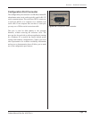
Figure 4 - 7 DB-25M, Generator Output Cable
Connector
1 3 5 7 9 11 13
15 17 19
21 23 25
13 11 9 7 5 3 1
25 23 21 19 17 15
Pin 20 (Bad Part Status Output)
Pin 20 is a digital active low status output that activates,
either momentarily or until the start of the next welding
cycle, when the welding parameters recorded during the
previous welding cycle are outside of the programmed
bad part limits. This output will be an open circuit when
a bad part has not been detected.
Pin 21 (Good Part Status Output)
Pin 21 is a digital active low status output that activates,
either momentarily or until the start of the next welding
cycle, when the welding parameters recorded during the
previous welding cycle do not exceed the programmed
suspect or bad part limits. This output will be an open
circuit after a welding cycle when either a suspect or
bad part has been detected.
Pin 22 (System Ready Status Output)
This status output signal will activate only when the
system is ready to activate ultrasound or begin a weld
cycle. Pin 22 is a digital active low status output that
activates when a weld processing cycle is completed and
the welding process control system is ready to start the
next welding cycle. This output will be an open circuit
when the welding process controller determines that
the next welding cycle cannot be started. This includes
system faults or ofine active, but not a process fault
like Overload.