


Page 21Page 20
iQ Series, Ultrasonic Generator/Power Supply LS User’s Manual
Section 4 – Standard Connections
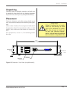
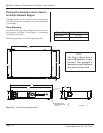
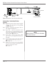
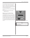
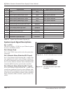
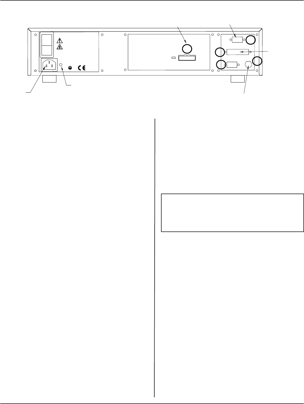
Figure 3 - 6 Generator - Rear View (low prole model)
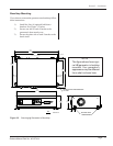
Automation Controlled Probe
System
Step 1. Ground the generator chassis using the supplied
14-Gauge wire, and attach it to the grounding
stud:A in Figure 3 -6.
Step 2. Optional – Ground the probe support. This is a
user–supplied 14-Gauge wire.
Step 3. Input Cable - Attach the automation control
cable from the user–supplied automation equip-
ment to the system input HD-15 connector, J2
on the I/O panel: B in Figure 3 -6.
Step 4. Output Cable - Attach an output cable - DB25
type - from J3 to your equipment to monitor sys-
tem status.
Step 5. Attach the high voltage coaxial cable from the
probe to the ultrasound output connector J1:
C in Figure 3 -6.
Step 6. Connect the AC power cord to the generator
IEC power inlet connector, and plug the other
end into an approved AC outlet:
D in Figure 3 -6.
NOTE
Refer to Section 10, Options for information
about other features.
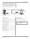
LINE VOLTAGE:
200-240 Vac
50/60Hz, 10A
PE
AC POWER
INLET
GROUNDING
STUD
J2
J3
J4
J7
J1
ULTRASOUND OUTPUT
INPUTS
OUTPUTS
J7 is optional.
I
0