


Page 79
Section 10 - Options
Dukane Manual Part No. 403-574-01
Connecting Cables
For stand-alone interfaces and securely installed panel
mounted interfaces:
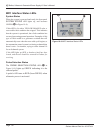
Rear Connections
Refer to Figure 10 -7 below, and complete these
connections.
1. Earth ground - Connect one end of a user-supplied
14-Gauge ground wire to the ground connection at
the rear of the MPC, A in Figure 10 -7. Connect the
other end of the wire to an earth ground potential at
the electrical box that supplies power to the equipment
(or to the equipment enclosure into which your system
is installed).
2. U/S (ultrasonic) cable (Dukane P/N 200-479-XX -
Order the correct cable length for your installation.)
- Connect one end of the cable to the left rear U/S con-
nector of the MPC interface, B in Figure 10 -7. The
other end of the cable connects to J1 of the ultrasonic
generator.
3. MPC Interface cable (Dukane P/N 200-1408-XX -
Order the correct cable length for your installation.)
- Connect one end of the cable to the right rear MPC
Interface connector, C in Figure 10 -7. The other
end of the cable connects to the MPC INTERFACE
connector on the ultrasonic generator.
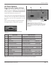
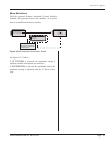
Figure 10 - 7 MPC Interface Rear Connectors
CA
B
Front Connections
Refer to Figure 10 -8 below.
Complete these connections.
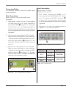
1. Probe Cable(s) - Beginning with PROBE 1, con-
nect one end of the cable (See Table 10 - IV below.)
to the U/S connector on the MPC’s front panel, D
in Figure 10 -7. Connect the other end of the cable
to the corresponding probe for your specic welding
application.
2. Repeat Step 1 for each of the remaining probes (in
sequence: 2, 3, 4, etc.) in your system.
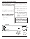
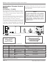
Figure 10- 8 MPC Interface Front Connectors
D
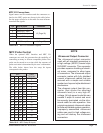
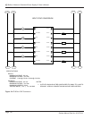
System
Frequency
Probe P/N Cable P/N :
MPC to Probe
20kHz
41C25
200-479-XX
41C27
30kHz 41A60R-129
200-615-XX
40kHz 41A40
Table 10- IV Probe Cables