


Page 31Page 30
iQ Series, Ultrasonic Generator/Power Supply LS User’s Manual
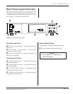
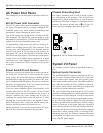
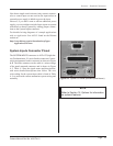
Section 4 – Standard Connections
Page 31Page 30
iQ Series, Ultrasonic Generator/Power Supply LS User’s Manual
Section 4 – Standard Connections
Dukane Manual Part No. 403-574-01
Pin 23 (Suspect Part Status Output)
Pin 23 is a digital active low status output that activates,
either momentarily or until the start of the next welding
cycle, when the welding parameters recorded during the
previous welding cycle are outside of the programmed
suspect part limits. This output will be an open circuit
after a welding cycle when a suspect part has not been
detected.
Pin 24 (Isolated Common)
Pin 24 is electrically isolated from chassis ground. This
common line should be connected to negative output
at a user-provided isolated 24VDC power supply. The
isolated NPN status output signals can drive PNP inputs.
Pin 25 (Not Used)
Pin 25 is an open connection.
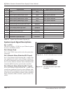
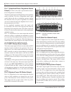
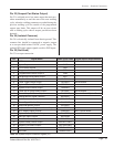
Pin Signal Name Cable Color Code Signal Option Requirements
1 +22V BLK
2 Spare Output WHT
3 +22V Power Ground RED
4 Programmable Status Output 1 GRN
5 Programmable Status Output 2 ORN
6 Ultrasound Active Status Output BLU
7 Any Fault Status Output WHT/BLK
8 Press Trigger Status Output RED/BLK Not Available
9 System Overload Status Output GRN/BLK
10 System Online Status Output ORN/BLK
11 Press Top of Stroke Status Output BLU/BLK Not Available
12 Current Loop OK Status Output BLK/WHT Remote Control Option Board
13 Analog Monitor Signal Common RED/WHT
14 Not Used GRN/WHT
15 Power Signal Monitor Output BLU/WHT
16 Amplitude Monitor Output BLK/RED
17 Amplitude/Power Regulation Status Output WHT/RED
18 MPC Ready Status Outputs ORN/RED MPC Option Board
19 System Power OK Status Output BLU/RED
20 Bad Part Status Output RED/GRN
21 Good Part Status Output ORN/GRN
22 System Ready Status Output BLK/WHT/RED
23 Suspect Part Status Output WHT/BLK/RED
24 Isolated Common RED/BLK/WHT
25 Not Used GRN/BLK/WHT
Table 4 - II System Output Connector Signals (J3)