


Page 15
Section 3 – Installation
Dukane Manual Part No. 403-574-01
Unpacking
Carefully open your shipping container, and make sure
it contains the items shown on the shipping documents.
Inspect all items, and report any damage immediately.
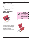
Placement
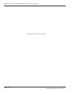
Generator placement and cable routing should permit
easy access and not interfere with normal system opera-
tion.
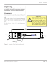
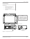
Allow at least 5 inches (13 cm) of space on both ends of
the generator chassis for air circulation. Allow a 3 inch
space (8 cm) at the rear of the chassis for cable clear-
ance.
See Specications, Section 11, for detailed generator
drawings.
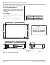
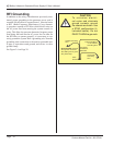
CAUTION
Allow 5 inches for air venti-
lation at the cooling air inlet
and at the exhaust air outlet.
The fan draws in fresh air
to cool the internal compo-
nents, reduce thermal gradients
and increase component life.
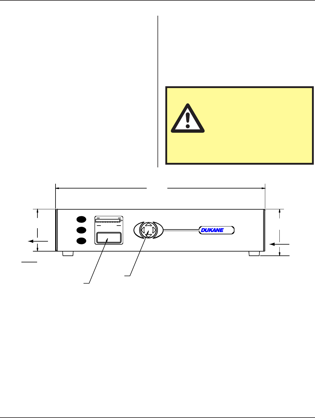
Figure 3 -3 Generator - Front View (low prole model)
8060 100400 20
SYSTEM POWER OUTPUT LEVEL
SYSTEM OPERATING MODE
LOAD
OVER
ON
LINE
OFF
LINE
POWER
TEST
OPERATOR
CONTROLS
IN
[mm]
3.81
[96.8]
3.45
[87.53]
17.16
[435.86]
OPERATOR
DISPLAY
COOLING AIR
INLET
EXHAUST AIR
OUTLET
I
N
F
O
O
N
/
O
F
F
L
I
N
E
T
E
S
T
C
A
N
C
E
L
E
N
T
E
R
i
Q