


Page 82
iQ Series, Ultrasonic Generator/Power Supply LS User’s Manual
Dukane Manual Part No. 403-574-01
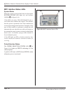
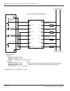
Remote Amplitude Control
Module
Part Number - 110- 4183
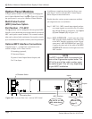
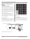
This optional module enables remote control of output
amplitude of the iQ system. The control interface is a
4–20mA current loop. The current loop connector and
fault indicator are shown below in Figure 10–12. The
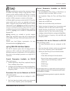
output can be adjusted from 36% to 100%. The scale
factor is a 4% amplitude change for each mA change. A
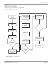
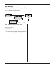
graph of amplitude output as a function of loop current
is shown in Figure 10-11. The current loop compliance
voltage is 6 volts minimum.
Failure to provide at least 4mA of loop current is sensed as
a fault and will produce minimum amplitude output.
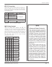
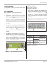
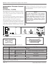
The current loop fault indicator is a bi–color LED. It is
green when the current is between 4 and 20mA and red
when the current is below 2mA.
Current Loop Fault
If a current loop source is not available, an external +24VDC
power supply can be connected to the POS and NEG
terminals of J7. (See Figure 10-12.) A +22VDC supply is
also available on System Output Pins 1(+) and 3(-).
5mA0mA
20%
0%
40%
60%
80%
100%
10mA 15mA 20mA
4mA
Current
Loop
Fault
Region
36%
Figure 10-11 Current Loop Transfer Function Graph
Future Availability
In the future, Remote Power Regulation Control will
become available. This option module will be able to
remotely control the power regulation setpoint using new
user-selection menu choices made from the front panel.
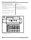
Figure 10-12 Remote Amplitude Control Module
LINE VOLTAGE:
200-240 Vac
50/60Hz, 10A
PE
J1
J4
J3
J2
J7
SYSTEM INPUTS
SYSTEM OUTPUTS
CONFIGURATION
U/S
CURRENT LOOP
INPUT
STATUS
POS
NEG
SHIELD
E-STOP
Current Loop Fault Indicator - Green/Red LED
Current Loop Connector