


Page 29Page 28
iQ Series, Ultrasonic Generator/Power Supply LS User’s Manual
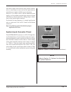
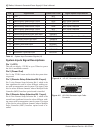
Section 4 – Standard Connections
Page 29Page 28
iQ Series, Ultrasonic Generator/Power Supply LS User’s Manual
Section 4 – Standard Connections
Dukane Manual Part No. 403-574-01
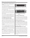
Pin 7 (Any Fault Status Output)
Pin 7 is a digital active low status output that activates
whenever any fault condition is detected that inhibits
ultrasound output and normal system operation. This
output will be an open circuit when no system fault
conditions are detected. Any Fault output remains active
until cleared by the System Latch Reset input or by the
start of the next weld cycle.
Generator faults that will activate the Any Fault output:
• Overload (Average, Peak, Frequency)
• Over Temperature Fault
• System Power Fault
• Current Loop Fault
Pin 8 (Press Trigger Status Output)
NOT AVAILABLE.
Pin 9 (System Overload Status Output)
Pin 9 is a digital active low status output that activates
whenever any overload condition is tripped. Activation
of the overload status output signal could be caused by
an Average, Peak or Frequency overload condition. After
the overload status output activates, it will remain active
until the next ultrasound activation cycle begins and
this output will automatically reset. This output will be
an open circuit when no overload conditions have been
detected.
Pin 10 (System On-Line Status Output)
Pin 10 is a digital active low status output that activates
when the system is in the ONLINE operating mode, which
enables the activation of the ultrasonic output. This output
will be an open circuit if the system is switched to the
OFFLINE operating mode, or if an externally connected
E-Stop has been activated, and the open circuit prevents
the start of a welding cycle or activation of the ultrasound
output. Note that an automation controlled process can
not weld any parts, if the system is, accidentally or
otherwise, switched to the OFFLINE operating mode.
Pin 11 (Press Top of Stroke Status Output)
NOT AVAILABLE.
Pin 12 (Current Loop OK Status Output)
This status output signal will activate only when a Remote
Amplitude Control Board is installed in the system. Pin
12 is a digital active low status output that activates when
the current loop input to the remote control option board
is connected and working normally. This output will be
an open circuit when the current loop input signal is too
low for proper system operation (less than 2mA). This
may be due to a broken wire connection, a failed current
loop controller or the current loop input wired incorrectly
to the input terminal block.
Pin 13 (Analog Monitor Signal Common)
Pin 13 is the signal common (ground) connection for all
of the analog monitor signals (on Pins 14, 15 and 16).
This signal common pin is connected to system chassis
ground and is not isolated from the generator chassis. This
is an analog signal ground connection. Do not connect
anything to this ground connection, except the wiring to
the inputs of the analog instrumentation devices used to
measure the monitor output signals.
Pin 14 (Not Used)
Pin 14 is connected to the system chassis ground.
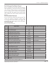
Pin 15 (Power Signal Monitor Output)
Pin 15 is an analog output signal used to monitor the
power output from the welding system. The scaling on
this output signal is as shown below:
15kHz, 20kHz, 30kHz and 40kHz systems:
1 Watt = 0.001 VDC (1mV per Watt)
Example: • 20kHz system measures 0.525 VDC on
Power Monitor Output = 525 Watts.
Pin 16 (Amplitude Monitor Output)
Pin 16 is an analog output signal used to monitor the
system amplitude setting. The scaling on this output
signal is 100% amplitude = 10.0 VDC, or 0.1 VDC
per 1% amplitude. This monitor signal output would
typically be used when a remote control option board is
installed in the system. The automation control system
will adjust the system’s amplitude setting remotely, using
a 4-20mA current loop attached to the input of the remote
control board. Using this monitor output, the control
system can verify that the amplitude is set to the expected
programmed amplitude level.