


Page 74
iQ Series, Ultrasonic Generator/Power Supply LS User’s Manual
Dukane Manual Part No. 403-574-01
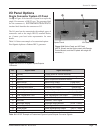
AC Power Inlet Panel
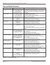
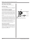
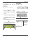
The optional AC power inlet panel is described here.
AC Power Cord
The AC power cord (A in Figure 10-2) is appropriately
rated and permanently mounted to the power inlet panel.
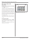
Power Switch/Circuit Breaker
The power switch/circuit breaker (B in Figure 10-2) has
a rocker type actuator switch that will activate or deacti-
vate the AC power to the system. The power ON position
is marked with the internationally recognized I symbol,
the power OFF position is marked with the 0 symbol.
This power switch also integrates an appropriately sized
over-current protection circuit breaker function in the
generator.
If an over-current condition trips the circuit breaker, it
will automatically switch to the OFF position. If the over-
load current that caused the circuit breaker to trip is due
to a transient condition, the circuit breaker can be reset by
switching the actuator back to the ON position. If when
resetting the circuit breaker after it has tripped, it imme-
diately trips again, there is likely an internal system mal-
function, and the generator will require service.
Do not repeatedly try to reset the circuit breaker. If it trips,
this will only cause more damage to the generator.
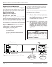
Chassis Ground Stud
The chassis ground stud is used to attach a protective earth
ground to the generator. This will aid in the suppression
of electrical interference or radio frequency interference
(RFI) that is common in an industrial environment. The
chassis ground stud is C in Figure 10-2. Proper system
grounding is discussed in Section 3.
Figure 10 - 2 120VAC Power Inlet Panel
LINE VOLTAGE:
100-120 Vac
50/60Hz, 10A
PE
120 volt line cord
I
0
A
B
C