


Page 23Page 22
iQ Series, Ultrasonic Generator/Power Supply LS User’s Manual
Section 4 – Standard Connections
Page 23Page 22
iQ Series, Ultrasonic Generator/Power Supply LS User’s Manual
Section 4 – Standard Connections
Dukane Manual Part No. 403-574-01
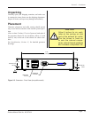
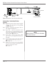
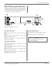
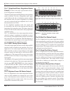
Rear Panel Layout Overview
This section provides an overview of the generator rear
panel layout, which includes panel areas dedicated to var-
ious standard system functions and options that are avail-
able. Figure 4 - 1 illustrates the panel layout.
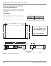
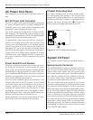
AC Power Inlet Panel
A IEC Power Inlet Connector – Attaches to an IEC style
power cord.
B Power Switch – Circuit Breaker – Used to switch
system power ON and OFF.
C Chassis Grounding Stud – Chassis connection for a
protective earth ground.
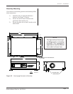
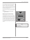
The System I/O Panel
D System Input Connector – Connections for system
control input signals.
E System Output Connector – Connections for system
status output signals.
F Ultrasound Output Connector – Coaxial high voltage
connection to ultrasonic stack.
G Conguration Port Connector – Digital control port
to modify system parameters.
LINE VOLTAGE:
200-240 Vac
50/60Hz, 10A
PE
I
0
Figure 4 - 1 Generator Rear Panel
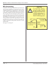
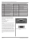
Options Module Panel
(A blank panel is installed on standard systems.)
K An option module can be installed here.
NOTE
See Section 10, Options for
more information.
A
B
C
D
E
F
GK