


Page 25Page 24
iQ Series, Ultrasonic Generator/Power Supply LS User’s Manual
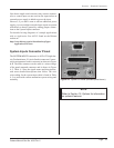
Section 4 – Standard Connections
Page 25Page 24
iQ Series, Ultrasonic Generator/Power Supply LS User’s Manual
Section 4 – Standard Connections
Dukane Manual Part No. 403-574-01
website at:
http://www.dukane.com/us/downloads.asp?type=
Application%20Notes
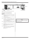
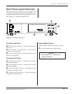
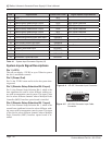
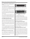
System Inputs Connector Pinout
The SYSTEM INPUTS connector is a HD-15F (high den-
sity D-subminiature 15 circuit female) connector. Connec-
tor pin assignments for this connector are shown in Figure
4 - 4. The male connector on the cable is a mirror image
of the panel mounted connector and is shown in Figure
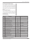
4 - 5. Table 4 - I lists the signal names and descriptions,
with more detailed descriptions that follow. The wire
color coding for the system input cable is listed in Table
4 - I, to assist with custom automation system wiring and
assembly.
NOTE
Refer to Section 10, Options for information
on optional features.
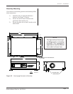
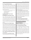
Figure 4 - 3 System I/O Panel (standard panel shown)
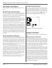
Note that a simple switch closure (relay contact) connect-
ed to a control input can not activate the input unless an
external power supply is added to power the input.
However, if you don’t want to add an additional power
supply, you can congure switch closure inputs to operate
referenced to chassis ground by adding jumper connec-
tions to the System Inputs connector.
For detailed wiring diagrams of example applications
refer to Application Note AN502 found on the Dukane