


Page 27Page 26
iQ Series, Ultrasonic Generator/Power Supply LS User’s Manual
Section 4 – Standard Connections
Dukane Manual Part No. 403-574-01
Page 27Page 26
iQ Series, Ultrasonic Generator/Power Supply LS User’s Manual
Section 4 – Standard Connections
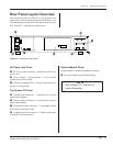
System Inputs Signal Descriptions
Pin 1 (+22V)
This pin can supply +22VDC at up to 250mA to power
the user’s automation controls.
Pin 2 (Power Gnd)
Pin 2 is the 22VDC return and is tied to the system chas-
sis ground.
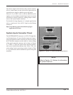
Pin 3 (Remote Setup Selection Bit 0 Input)
Pin 3 is the Remote Setup Selection Bit 0, which is the
least signicant bit used to select different welding set-
ups with an automation control system. This input is also
used to select different channels when a Multiple Probe
Controller (MPC) Interface option board is installed.
Pin 4 (Remote Setup Selection Bit 1 Input)
Pin 4 is the Remote Setup Selection Bit 1, which is the
second least signicant bit used to select different weld-
ing setups with an automation control system. This input
is also used to select different channels when a Multiple
Probe Controller (MPC) Interface option board is in-
stalled.
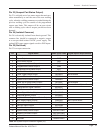
Pin Signal Name Cable Color Code Signal Option Requirements
1 +22V BLK
2 Power Ground WHT
3 Remote Setup Selection Bit 0 Input RED MPC Option Required
4 Remote Setup Selection Bit 1 Input GRN MPC Option Required
5 Remote Setup Selection Bit 2 Input ORN MPC Option Required
6 Remote Setup Selection Bit 3 Input BLU MPC Option Required
7 Remote Setup Selection Bit 4 Input WHT/BLK Not Used
8 Ultrasound Activation/Cycle Start Input RED/BLK
9 Automation Thruster Control Input GRN/BLK Automation Thruster Board Required
10 Front Panel Control Lock Input ORN/BLK
11 Press Inhibit for Hand Probes BLU/BLK Hand Probe
12 System Latch Reset Input BLK/WHT
13 Isolated Common RED/WHT
14 Not Used GRN/WHT
15 Automation Cycle Stop Input BLU/WHT
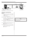
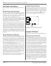
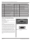
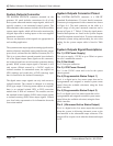
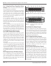
Figure 4 - 4 HD-15F, Generator Input Connector
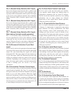
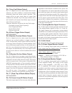
Figure 4 - 5 HD-15M, Generator Input Cable
Connector
1 2 3 4 5
6
10
11 12 13 14 15
5 4 3 2 1
5 4 3 2 1
15 14 13 12 11
15 14 13 12 11
6
6
10
10
Table 4 - I System Input Connector Signals (J2)