


Page 19
Section 3 – Installation
Dukane Manual Part No. 403-574-01
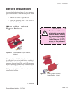
CAUTION
The power cord is equipped
with a three-prong, ground-
ed-type plug for your safety.
Whenever a two-slot re-
ceptacle is encountered,
we strongly recommend
that it is replaced with
a p ro pe r l y gr ou nd ed
three-lead receptacle.
Have a qualified electri-
cian do the replacement in
accordance with the Na-
tional Electrical Code and
local codes and ordinances.
DO NOT cut off the power
cord grounding prong or
alter the plug in any way.
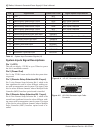
Table 3 - II Standard IEC AC Power Cord Part Numbers
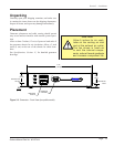
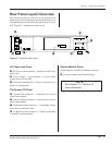
Connecting Cables
(Quick Start Guide)
Details about the various system connectors and their pin
assignments are covered in Section 4.
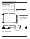
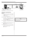
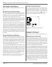
Manually Operated Probe System
(Hand Probe)
Step 1. Ground the generator chassis using the supplied
14-Gauge wire, and attach it to the grounding stud:
A in Figure 3 -6.
Step 2. Attach the hand probe’s HD–15 system input con-
nector to J2 on the I/O panel: B in Figure 3 -6.
Step 3. Attach high–voltage coaxial cable to J1, the ultra-
sound output connector: C in Figure 3 -6.
Step 4. Connect the AC power cord to the IEC power inlet
connector on the ultrasonic generator (D in Fig-
ure 3 -6), and plug the other end into an approved
AC outlet.
Power Cords
The AC line cords supplied with the standard generators
are matched to the ultrasonic output power rating and the
continent of specied use. See Table 3-II.
Continent of Use Power Cord
Part Number
Power
North America
200 - 1110 240V, 15A
200 - 1541 240V, 10A
Continental Europe
200 - 1111 240V, 16A
200 - 1542 240V, 10A
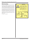
NOTE
Refer to Section 10, Options for informa-
tion about optional features.