


Page 75
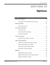
Section 10 - Options
Dukane Manual Part No. 403-574-01
I/O Panel Options
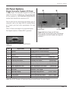
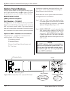
Single Connector System I/O Panel
See B in Figure 10-4 where the I/O panel is set up for the
single I/O connector, a HD15F type. The generator label
for this connector is, SYSTEM INPUTS/OUTPUTS.
Another label identies the connector as J12.
The I/O panel can be customized with multiple types of
connectors such as the single HD15F, terminal blocks,
etc. Contact your local sales representative for more
details.
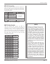
Table 10-I shows an example of a customized option:
Pins/Signals duplicate a Dukane DPC-I generator.
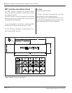
5 4 3 2 1
5 4 3 2 1
15 14 13 12 11
15 14 13 12 11
6
6
10
10
Figure 10 - 3 HD15F for System Inputs/Outputs
Connector
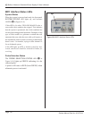
Figure 10- 4 Option Panel and I/O Panel
(NOTE: Shown are the Option panel with Remote
Control Module, and the I/O panel with single I/O
connector.)
Option Panel
I/O Panel
B
Pin Signal Name Signal Description
1 +22VDC Current limited to 250mA maximum
2 Ground 22VDC Return (chassis ground)
3 Ground Status Outputs/Driver/Monitor Return
4 Status Driver Status Driver Output (1 Amp max.)
5 Ultrasound Active Status Ultrasound Status Output (Active Low)
6 Overload Fault Status Overload Fault Output (Active Low)
7 Isolated Operate Input Common Isolated Operate Input Common (7 & 8) JU726
8 Operate Input Sw Closure Operate Inut (2 & 8) JU724/725
9 Over Temperature Fault Over Temperature Fault Output (Active Low)
10 System Fault System Fault Output (Active Low)
11 Not Used Reserved - HPPI Signal
12 Amplitude Setting Amplitude Setting Monitor (10.0V = 100%)
13 Power Signal Common Power Signal Common
14 Power Signal Power Signal Monitor Output (1mV = 1 Watt)
15 Loop Fault Current Loop Fault Output (Active Low)
Table 10- I HD15F Example of Customized System Inputs/Outputs Connector Signals
A