


Page 40
iQ Series, Ultrasonic Generator/Power Supply LS User’s Manual
Dukane Manual Part No. 403-574-01
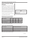
Start-up Sequence
After all connections have been completed,
1. Push the rear panel AC breaker switch to ON.
The generator begins its self-diagnostics sequence.
2. POWER TEST ashes (RED) for several seconds.
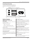
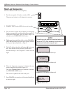
3. First, the entire System Power Output Level bargraph
lights up momentarily (verifying that all bar graph LED
segments are functional). Next, two short “beeps” are
sounded as the OVERLOAD LED ashes.
4. The System Operating Mode shifts to either ONLINE or
OFFLINE depending on what was previously selected.
See System Operating Mode on Page 31.
5. The LCD display identies the Dukane iQ Series type
rst. Then another screen provides system detail.
See the Start-up (1 and 2) Figures 5-3 and 5-4 to the
right.
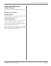
6. When the diagnostics sequence is nished, the next
screen to appear will look like Figure 5-5.
This is the Process Data screen, and that is linked to
the OPERATE MODE menu.
This screen is updated after each weld cycle.
7. Press CANCEL twice and you will be at the Main Menu
as shown at right.
LOAD
8060 100
OVER
400 20
SYSTEM POWER OUTPUT LEVEL
SYSTEM OPERATING MODE
POWER
TEST
# 1 PART COUNT 125
WELD TIME 0.080 S
POWER 1050 W
ENERGY 350 J
Figure 5 - 5 LCD Display at Start-up 3
Figure 5 - 6 Main Menu
# 1:
OPERATE MODE
PROCESS SETUP
HARDWARE SETUP
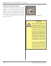
NOTE
A welding cycle cannot be started when the
mode is OFFLINE because this blocks the
ultrasound activation signal input.
# 1 PART COUNT 0
WELD TIME 0.0000 S
PEAK POWER 0 W
ENERGY 0 J
Figure 5 - 4 LCD Display at Start-up 2
AUTOMATED PROBE
TIME + ENERGY
20kHz 2400 W SYSTEM
Figure 5 - 3 LCD Display at Start-up 1
DUKANE iQ LS SERIES