


Page 37
Section 5 – Standard System Status and Controls
Dukane Manual Part No. 403-574-01
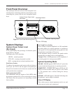
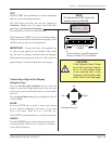
Front Panel Overview
This section provides an overview of the front panel’s two
main functions: monitoring (with the system displays), and
controlling the system (with the user navigation control
keys).
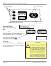
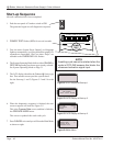
LOAD
8060 100
OVER
400 20
SYSTEM POWER OUTPUT LEVEL
SYSTEM OPERATING MODE
ON
LINE
OFF
LINE
POWER
TEST
# 1 PART COUNT 125
WELD TIME 0.080 S
POWER 1050 W
ENERGY 350 J
I
N
F
O
O
N
/
O
F
F
L
I
N
E
T
E
S
T
C
A
N
C
E
L
E
N
T
E
R
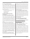
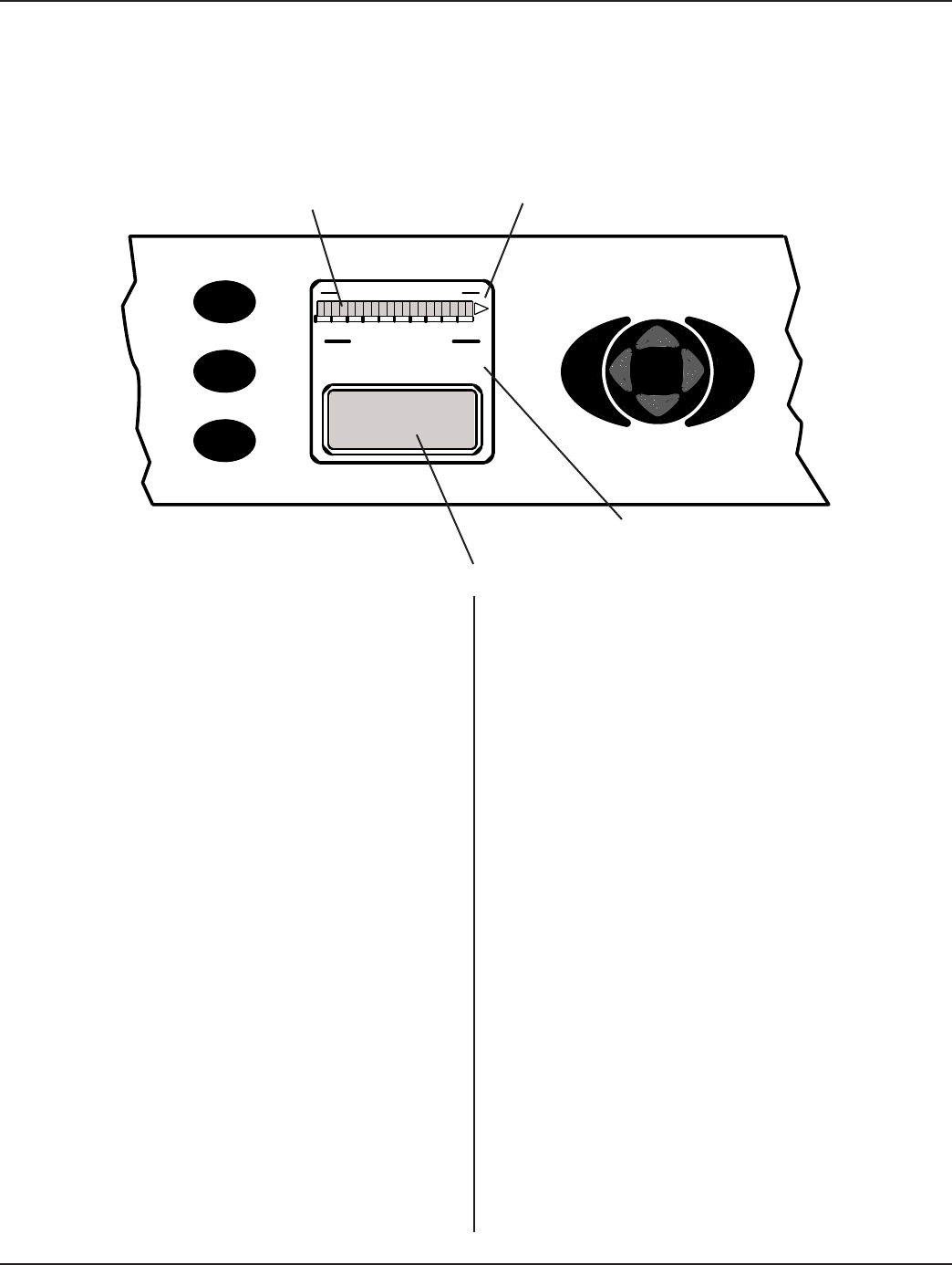
Figure 5 - 1 Front Panel Monitoring Detail
System Power Output Level
Bar Graph
Overload Indicator
System Operating Mode
4-line LCD Display
System Displays
System Power Output Level
(Bar Graph)
A bar graph displays the percentage of ultrasonic power
being drawn by the load.
The display uses LED’s that show:
GREEN - normal operation.
YELLOW - warning of potential overload.
RED - warning that an overload condition exists.
Peak Detect Feature
To indicate the maximum peak power achieved during a
weld cycle, the LED in the bar graph corresponding to
the peak level remains on (for about one second) after the
weld cycle has been completed.
Flash on Overload at 90%
The OVERLOAD indicator begins to ash (RED) when
the generator produces 90% of the overload power rating.
This feature alerts the operator to an impending overload
fault condition.
Bar Graph Power Scaling
Power scaling is related to amplitude. At 100% amplitude
the whole graph is lit, and the generator is operating at
100% power. At 50% amplitude the entire graph is lit, and
the generator is operating at 50% power.
If the amplitude setting is lowered, the graph rescales
automatically according to the revised amplitude.
Example: With a 1200W generator, at 50% amplitude, if
the whole graph is lit, that represents 600W.
System Operating Mode
ON LINE - ONLINE appears GREEN after AC power has
been activated and the generator is operating normally.
POWER TEST - POWER TEST appears RED and will
ash for several seconds when AC power is rst turned
on. The generator runs a self-test during the start-up
sequence.
OFFLINE - OFFLINE appears YELLOW indicating that
the generator’s power output is disabled.
4-line LCD Display
This is where process control parameters can be set, and
where process results can be monitored.