


Page 63
Section 8 – Troubleshooting
Dukane Manual Part No. 403-574-01
No Ultrasonic Output
Probe
Make sure that the probe coaxial cable is connected to the
generator ultrasonic output connector J1. Basic generator
models have the BNC connector on the rear panel. Also,
make sure the probe stack was properly assembled.
Cables
Make sure that both the U/S coaxial and system I/O cables
are securely connected. You must activate the ultrasound
activation input to Pin 8 on the system input HD-15
connector either by the hand probe’s control cable or
with a custom automation input signal. Refer to Table 4-I,
Generator Input Signals, for details.
Place the generator OFFLINE, and:
1. Check the coaxial cable for any signs of damage which
may result in an open circuit preventing the cable
from transmitting the signal from the generator to the
probe.
2. If you have a mounted probe, replace the coaxial cable
with a known good cable.
3. If you are using a hand probe, try a different known
good probe to determine if the problem is related to the
generator or the external cables and probe.
Generator
The generator will not produce an output signal when
triggered if it is ofine. (If the generator is OFFLINE, the
system mode indicator shows OFFLINE in yellow.) To
change the system to ONLINE, press the ON/OFFLINE
mode key. When ONLINE, the system mode indicator
shows ONLINE in green. Verify that at least one segment
on the LED bar graph lights when the ultrasonic activation
input signal starts a welding cycle.
Operate Input
If you are using a hand probe, make sure the control cable
and adapter cable are securely connected to the system I/O
connector. The trigger switch on the hand probe activates
the ultrasonic output through the control cable.
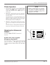
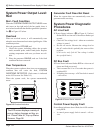
Figure 8 - 1 Cable End of System I/O Connector
NOTE
The cable end of the system I/O con-
nector is a mirror image of the panel
connector. Figure 8 - 1 below shows
the cable pinout. Make sure you have
correctly wired the connector if you are
using custom automation signals.
Also refer to Table 4-II for the cable
color pin assignment.
1 2 3 4 5
6
10
11 12 13 14 15