


Rev. B
Sand Pro 2020/3020/5020Hydraulic System (Rev. A) Page 4 – 48
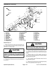
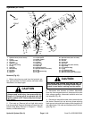
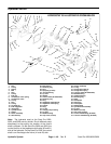
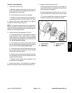
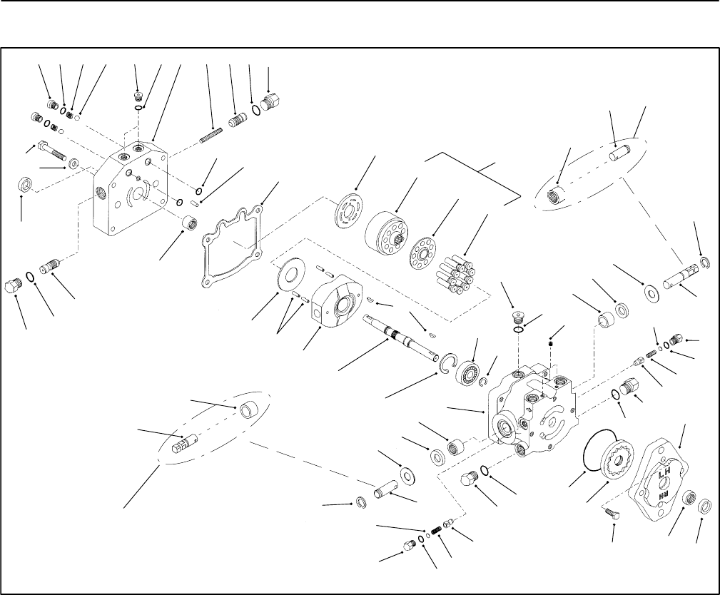
Hydrostat Service
1. Plug
2. O–ring
3. Spring
4. Ball
5. Plug
6. O–ring
7. End cap
8. Acceleration valve spring
9. Acceleration valve
10. O–ring
11. Plug
12. O–ring
13. Locating pin
14. End cap gasket
15. Valve plate
16. Cylinder block
17. Spider
18. Piston assembly
19. Woodruff key
20. Ball bearing
21. Retaining ring
22. Plug
23. Pipe plug (2 used)
24. Journal bearing
25. Lip seal
26. Washer
27. Control shaft (SP 2020/3020)
28. Retaining ring
29. Plug
30. Implement relief shim kit
31. Implement relief spring
32. Poppet
33. Plug
34. O–ring
35. Charge pump housing
36. Lip seal
37. Needle bearing
38. Cap screw (4 used)
39. Gerotor assembly
40. O–ring
41. Charge relief shim kit
42. Charge relief spring
43. Trunnion shaft (SP 2020/3020)
44. Needle bearing
45. Variable housing
46. Retaining ring
47. Shaft
48. Swashplate
49. Spring pin
50. Thrust plate
51. Shaft bearing
52. Cylinder block assembly
53. Lip seal
54. Washer (4 used)
55. Cap screw (4 used)
56. Control shaft/bearing (SP 5020)
57. Trunnion shaft/bearing (SP 5020)
Figure 40
30
31
32
33
34
35
36
37
38
39
40
32
42
29
43
44
45
46
47
48
49
50
51
9
12 34 5 678 910
16
17
19
20
21
22
10
23
24
25
26
27
28
29
11
12
13
14
15
2
2
25
26
28
41
33
34
10
11
53
54
55
18
27
43
52
24
44
56
57
HYDROSTAT IS ILLUSTRATED FROM BELOW
Note: The hydrostat used on the Sand Pro 2020,
3020, and 5020 are very similar. Due to different pump
attachment to the engine, the location of the control
shaft is different. On the Sand Pro 2020 and 3020, the
control shaft is on the implement relief valve (30 and 31)
side of the hydrostat. On the Sand Pro 5020, the control
shaft is on the charge relief valve (41 and 42) side.