


Rev. B
Sand Pro 2020/3020/5020 Hydraulic System (Rev. A)Page 4 – 23
Procedure for Charge Relief Valve (R2) and Imple-
ment Relief Valve (R1) Pressure:
1. Make sure hydraulic oil is at normal operating tem-
perature by operating the machine for approximately 10
minutes.
2. Park machine on a level surface with the attach-
ments lowered. Make sure engine is off. Make sure the
parking brake is engaged.
CAUTION
An attachment must be installed to the lift cylin-
der for the performance of this test to prevent
personal injury and damage to the machine.
3. Read Precautions for Hydraulic Testing.
NOTE: On the SP 2020/3020, special hydraulic fittings
are required to fit the test gauge into the hydrostat test
port because of the engine base plate (see Hydraulic
Test Fittings in the Special Tools section of this Chapter).
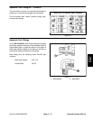
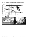
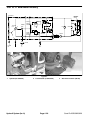
4. Remove plug and install pressure gauge to the hy-
drostat charge test port.
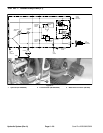
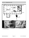
NOTE: If only implement relief valve (R1) pressure is to
be measured, an alternate pressure gauge location is to
install a T–connector with pressure gauge in series with
the hose from the pump and the T–fitting on the lift valve
(Figure 14).
5. Make sure that traction pedal and lift control lever
are in neutral and the parking brake is engaged.
6. After installing pressure gauge, start engine and run
at low idle speed. Check for hydraulic leakage and cor-
rect before proceeding with test.
7. Operate engine at full speed (3150 +
50 RPM).
Verify pump hub speed with a phototac.
8. The pressure gauge will display system charge
pressure and should read from 170 to 380 PSI. Record
test results.
9. If the specification is not met, replace charge relief
valve (R2) (see Hydrostat Service in this Chapter).
10. With the engine still running at full speed (3150 +
50
RPM), lower attachment. Hold lift lever in the lower posi-
tion to allow the implement relief valve to activate. Pres-
sure gauge should read from 700 to 1000 PSI. Record
test results.
11. If specification is not met, replace implement relief
valve (R1) (see Hydrostat Service in this Chapter).
12. Shut off engine.
13. Disconnect gauge and fittings from the hydrostat
charge test port. Install and tighten plug to test port.
14. Make sure hydraulic tank is full (see Check Hydrau-
lic System Fluid).
Hydraulic
Systems