


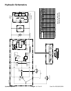
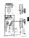

Hydraulic Flow Diagrams
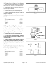
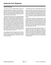
Traction Forward
The traction circuit of the hydraulic system consists of a
hydrostat connected in a closed loop circuit to three or
-
bital vane wheel motors. Hydraulic fluid losses are de-
signed to occur from case drain leakage of the traction
pump (P1) and bleed off from the right wheel motor (M1).
These losses are replenished by the charge pump (P2),
which is integral to the hydrostat.
The engine drives traction pump (P1) directly through a
coupling. The traction pump is a variable displacement
piston pump. The traction pedal connects through a link
-
age to the trunnion shaft and swash plate of the pump.
With the engine running and the traction pedal in the
neutral position, P2 supplies no flow to the wheel mo
-
tors. When the traction pedal is pressed to the forward
position, the linkage from the pedal positions the swash
plate in the traction pump so oil flows out port B. Oil flow
out of port B goes to the wheel motors and turns them
in the forward direction. On the SP 5020, the oil flow
goes through the front motor first and then through the
left and right rear wheel motors. Oil flowing out of the
wheel motors returns to port A of the hydrostat and is
continuously pumped out of port B.
The hydrostat uses a small amount of hydraulic fluid for
internal lubrication. Fluid is designed to leak across
pump parts into the case drain. This leakage results in
the loss of hydraulic fluid from the closed loop circuit that
must be replenished.
The charge pump (P2) is a fixed displacement gerotor
pump. It is driven directly off the traction pump. The
pump replenishes the closed loop circuit with fluid from
the tank. The charge relief valve (R2) supplies sufficient
head so that charge pump flow is guided to the low pres
-
sure side of the traction circuit through one of two check
valves. Pump flow in excess of replenishment require
-
ments is relieved through the charge relief valve back to
the tank.
The right wheel motor bleeds off a small amount of hy-
draulic fluid for cooling of the closed loop circuit. This
bleed off happens in the forward direction only. The high
pressure side of the motor forces a shuttle spool to shift
against a spring. The pressure drop across the motor
causes a small amount of fluid to bleed off through a
fixed orifice on the low pressure side of the motor and
then through the shuttle spool. This bleed off returns to
the tank through the oil cooler.
The acceleration valves reduce the rate of change in ac-
celeration (jerkiness) when hydrostat output is in-
creased by the action of the operator. An increase of
pressure on the output side of the hydrostat will by–pass
some pump flow to the low pressure side of the pump.
The valve on the high pressure side closes at a predeter
-
mined rate as pressure increases. This gives the hy-
drostat a smooth acceleration rate when the swashplate
is stroked rapidly.
Hydraulic System (Rev. A) Page 4 – 8 Sand Pro 2020/3020/5020