


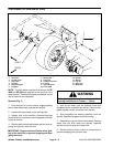
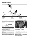
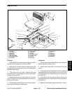
Brake Linkages (SP 2020/3020)
5
7
12
11
10
15
13
14
16
7
17
4
3
7
2
1
9
18
8
20
19
6
8
9
21
RIGHT
FRONT
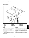
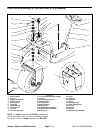
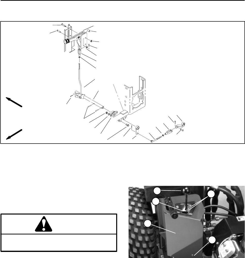
Figure 10
1. Cap screw
8. Clevis
15. Side flange bearing
2. Lock nut
9. Jam nut
16. Cap screw
3. Brake lever
10. Brake rod
17. Brake arm
4. Spacer
11. Adjusting rod
18. Adjusting rod
5. Clevis pin
12. Roll pins
19. Cotter pin
6. Flat washer
13. Spacer
20. Brake lever (to brake assembly)
7. Cotter pin
14. Flat washer
21. Clevis pin
Most parking brake linkage parts can be repaired or re-
placed without removing any interference. However, the
lift valve shroud must be removed to work on the parking
brake lever.
5
2
1
3
4
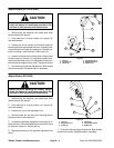
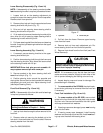
CAUTION
possible burns; allow engine and exhaust sys-
The muffler and exhaust pipe may be hot. Avoid
tem to cool before working near muffler.
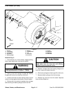
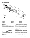
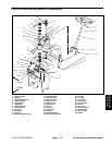
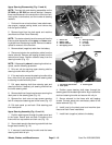
1. Remove knob from the lift lever. Remove both lock
nuts and cap screws securing the lift valve shroud, lift le
-
ver guide, and lift lever latch (Fig. 26).
2. Remove bottom front cap screw securing the lift
valve shroud to the frame. Pull shroud from the frame
(Fig. 26).
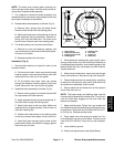
IMPORTANT:When removing the clevis from either
the brake rod or brake lever or the brake lever from
the cam shaft on the brake assembly, make sure to
matchmark both parts. Marking both parts will make
reassembly and brake adjustment easier.
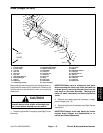
Figure 11
1. Knob 4. Lift lever guide & latch
2. Lock nut & cap screw 5. Cap screw
3. Lift valve shroud
3. Remove and replace parts as necessary to repair
brake linkages (Fig. 10).
4. Reinstall lift lever latch, lift lever guide, lift valve
shroud, and knob (Fig. 26).
IMPORTANT:Always check and adjust the brakes
anytime brake linkages are disassembled or re
-
paired (see Brake Adjustment).
Wheels, Brakes, and Miscellaneous Page 6 – 12 Sand Pro 2020/3020/5020