


Sand Pro 2020/3020/5020Hydraulic System (Rev. A) Page 4 – 30
Adjust Lift Lever (SP 2020/3020)
The lift lever should be adjusted if the attachment does
not float (follow ground contour) properly during opera-
tion.
1. Park machine on a level surface. Turn engine off
and engage parking brake.
2. Disconnect attachment from lift cylinder. Extend cyl-
inder part way.
3. Loosen capscrews and locknuts securing the lever
guide to the valve shroud.
4. Move lever guide until the cylinder moves freely
when the lift lever is in the detent position.
5. Tighten capscrews and locknuts to lock in adjust-
ment.
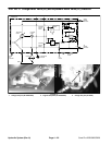
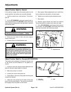
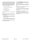
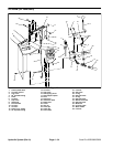
Figure 19
1. Cap screws
2. Lever guide
3. Lift lever
4. Detent position
3
1
2
4
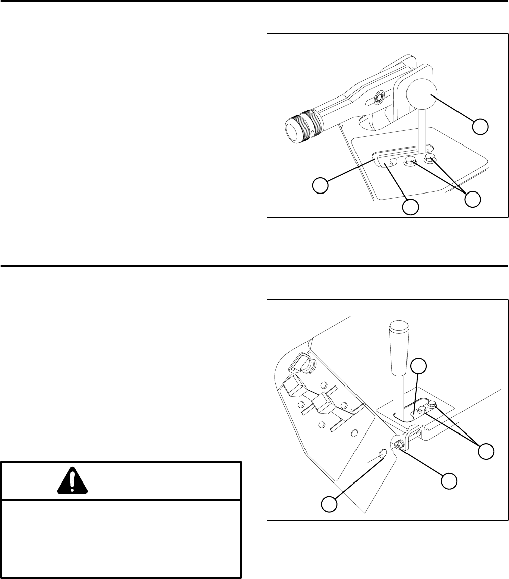
Adjust Lift Lever (SP 5020)
The lift lever detent plate should be adjusted if the at-
tachment does not float (follow ground contour) properly
during operation.
1. Park the machine on a level surface, turn engine off,
set parking brake, and block wheels.
2. Loosen both capscrews securing lift lever detent
plate to the fender and frame.
3. Insert a 3/16–inch hex key through the access hole
of the front fender and into the jacking screw of the lift
lever detent plate.
WARNING
The engine must be running so final adjust-
ment of the lift lever detent plate can be per-
formed. To guard against possible personal in-
jury, keep hands, feet, face and other parts of
the body away from the muffler, other hot parts
of the engine and other rotating parts.
4. Start engine.
5. With engine running and lift lever in the FLOAT posi-
tion, rotate jacking screw until the lift cylinder can be ex-
tended and retracted by hand.
6. Tighten both lift lever detent plate cap screws to se-
cure adjustment.
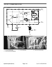
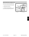
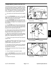
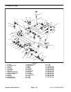
1. Cap screws
2. Detent plate
3. Access hole
4. Jacking screw
Figure 20
1
2
3
4