


Fenders (SP 5020)
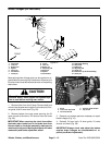
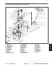
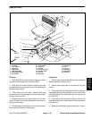
Left Fender(Seat Base )Removal (Fig. 44)
1. Park machine on a level surface, lower attachment,
stop engine, engage parking brake, and remove key
from the ignition switch.
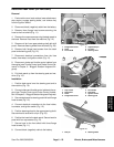
2. Pivot seat up. Separate seat rod from the base by
removing cotter pin and flat washer.
3. Separate base from frame by removing both lock
nuts, cap screws, flat washers, and spacers.
Seat Base Installation (Fig. 44)
3
4
1
1. Position seat base to the frame. Secure base to
Figure 24
frame with both spacers, flat washers, and lock nuts.
1. Cotter pin & flat washer 3. Lock nut
2. Seat rod 4. Cap screw & flat washer
2. Secure seat rod to the seat base with flat washer
and cotter pin. Pivot seat down.
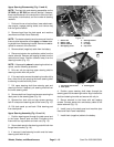
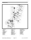
Right Fender Removal (Fig. 25 and 26)
1. Park machine on a level surface, lower attachment,
stop engine, engage parking brake, and remove key
from the ignition switch. Pivot seat up.
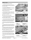
2. Disconnect black (negative) cable from the battery.
3. Remove knobs from throttle and choke controls.
Remove cap screws and lock nuts securing controls to
the right fender. Pull controls clear of the fender.
4
8
6
5
1
7
2
3
4. Remove hex nut and lock washer securing the igni-
tion switch to the right fender. Pull switch clear of the
Figure 25
fender.
1. Knob 5. Ignition switch
2. Throttle control 6. Hex flange head screw
3. Choke control 7. Lift lever
5. Unscrew knob from the lift lever. Remove both hex
4. Cap screw & lock nut 8. Carriage bolt & lock nut
flange head screws from the fender. Remove both car-
riage bolts and lock nuts securing the fender to the rear
panel.
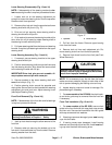
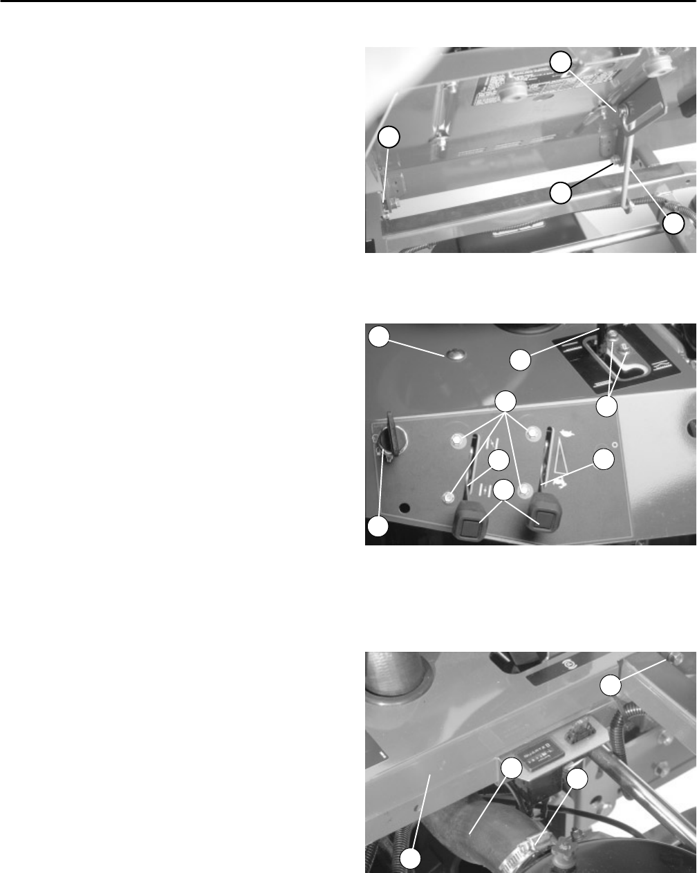
6. Loosen hose clamp and remove hose from air
cleaner. Remove cap screw, flat washer, lock nut secur
-
ing the right fender to the frame. Remove fender.
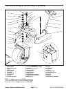
Right Fender Installation (Fig. 25 and 26)
1. Position right fender to the frame. Secure fender to
frame with hex flange head screws. Secure fender to
rear panel with both carriage bolts and lock nuts.
2. Secure fender to frame with cap screw, flat washer,
and lock nut. Secure hose to cleaner with hose clamp.
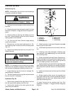
3
1
4
2
Figure 26
3. Secure ignition switch to the fender with lock washer
1. Hose clamp 3. Cap screw/flat washer
and hex nut.
2. Air cleaner hose 4. Right fender
4. Secure choke and throttle controls to the fender with
cap screws and lock nuts. Install knobs to both controls.
5. Connect black (negative) cable to the battery.
Wheels, Brakes, and Miscellaneous Page 6 – 24 Sand Pro 2020/3020/5020
2