


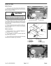
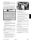
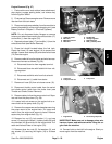
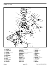
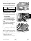
Engine Removal (Fig. 37)
1. Park machine on a level surface, lower attachment,
stop engine, engage parking brake, and remove key
from the ignition switch.
2. Pivot seat up. Remove engine cover. Remove move
litter box from fuel tank base.
3. Disconnect and remove battery from the machine to
prevent the possibility of the engine dropping on it (see
Battery Service in Chapter 5 – Electrical Systems).
NOTE: Do not disconnect brake linkages or remove
traverse rod when disconnecting the exhaust tube (17)
and muffler (1) from the engine (16).
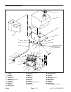
4. Separate exhaust tube (17) and muffler (1) from the
exhaust manifold (see Muffler Removal).
5. Close fuel shutoff located below the fuel tank.
Clamp fuel hose (12) near engine (16) to prevent fuel
spillage. Loosen hose clamp (28) and remove fuel hose
(12) from the engine.
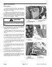
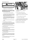
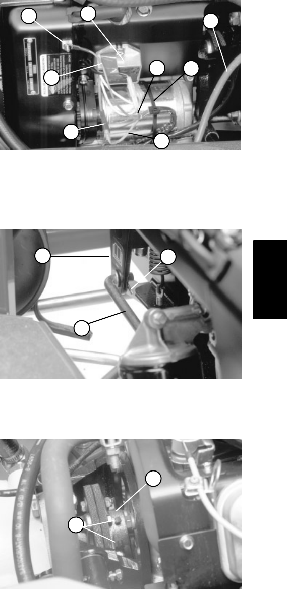
6. Remove cable tie from the starter and wire harness.
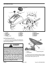
Disconnect harness as follows (Fig. 38):
A. Disconnect blue wire from magneto terminal.
B. Disconnect blue wire with fusible link from volt-
age regulator.
C. Disconnect red/white wire from fuel solenoid.
D. Disconnect red (+) cable from starter.
7. Remove air hose (33) from air cleaner cover (19).
8. Disconnect throttle control cable from the swivel
and choke control cable from the choke lever (see
Throttle and Choke Control Removal).
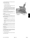
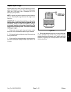
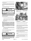
9. Remove cotter pin from the pump control rod. Sepa-
rate rod from the pump lever (Fig. 39).
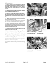
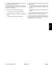
10. Loosen both set screws on the engine hub to re-
move hub from the pump shaft (Fig. 40).
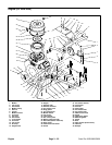
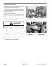
11. Remove four cap screws and lock washers securing
the pump mount to the engine block. Pull pump and
mount from the engine and secure to frame. Remove
square key from engine shaft (Fig. 41).
12. Remove hex nut (5), lock washer (11), and cap
screw (13) securing the black (–) battery cable (26) and
wire harness (43) ground wire to the engine block. Pull
cable and harness clear of the engine (16).
13. Remove three hex nuts (5), flat washers (3), and
cap screws (13) securing the engine (16) to its base
(15).
6
1
8
4
2
3
7
5
Figure 38
1. Cable on starter 5. Fusible link
2. Blue wire 6. Voltage regulator
3. Magneto terminal 7. Red/white wire
4. Blue wire 8. Red (+) battery cable
1
2
3
Figure 39
1. Cotter pin 3. Pump lever
2. Pump control rod
1
2
Figure 40
1. Engine hub 2. Set screw (pump hub)
IMPORTANT: Make sure not to damage wires, wire
harness, hoses, and cables are while lifting the en
-
gine from the machine.
14. Connect hoist or chain fall to the engine. Slowly re-
move engine from the machine.
Engine
Sand Pro 2020/3020/5020 Page 3 – 23 Engine