


Sand Pro 2020/3020/5020Hydraulic System (Rev. A) Page 4 – 74
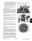
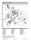
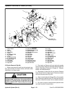
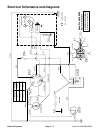
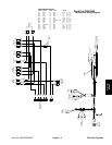
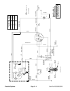
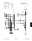
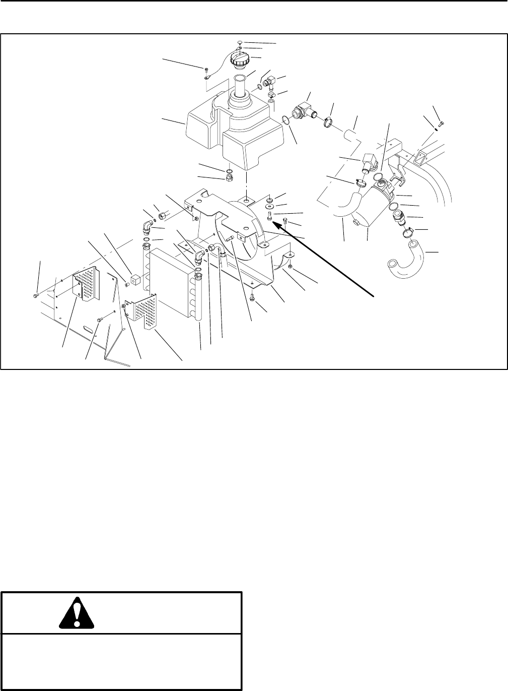
Hydraulic Tank and Oil Cooler (SP 5020)
1. Tether retainer
2. Tether
3. Tank cap
4. Filler screen
5. O–ring
6. 90
o
Hydraulic fitting
7. Hose clamp
8. O–ring
9. 90
o
hydraulic fitting
10. 90
o
hydraulic fitting
11. Hydraulic hose
12. Hose clamp
13. Lock washer
14. Cap screw
15. Hydraulic filter head
16. Straight hydraulic fitting
17. Hydraulic hose
18. Hydraulic filter element
19. Grommet
20. Flat washer
21. Cap screw
22. Cap screw
23. Lock nut
24. Lower shroud
25. Cooler mount
26. Self tapping screw
27. Socket head screw
28. Hydraulic hose
29. O–ring
30. Oil cooler
31. Left hand screen
32. Clinch nut
33. Right hand screen
34. T–nut
35. Rubber clamp
36. 90
o
hydraulic fitting
37. Hydraulic tube
38. Caution decal
39. Drain plug
40. Hydraulic tank
41. Shoulder screw
42. Cap screw
Figure 88
3132
33
34
35
36
37
38
39
40
41
1
2
3
4
5
6
12
8
10
7
16
17
18
19
20
21
22
23
24
25
26
27
28
29
30
11
13
14
15
7
7
11
8
8
9
14
42
5
23
29
5
30 to 60 ft–lb
35 to 69 kg–cm
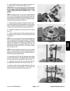
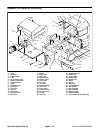
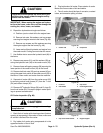
Oil Cooler Removal (Fig. 88)
1. Before removing any parts from the hydraulic sys-
tem, park machine on a level surface, set brake, lower
attachment, and stop engine.
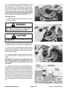
CAUTION
Operate all hydraulic controls to relieve system
pressure and avoid injury from pressurized hy-
draulic oil. Controls must be operated with the
ignition switch in OFF. Remove key from the igni-
tion switch.
2. Pivot seat up. Remove left and right side panels
from the machine. Remove left fender and seat (see Left
Fender (Seat Base) Removal in Chapter 6 – Wheels,
Brakes, and Miscellaneous).
3. Disconnect air hose from the air cleaner. Remove
lower shroud from the cooler mount. Disconnect control
rod from the pump lever (Fig. 89).
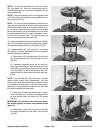
4. Clean around hydraulic fittings (36) on the oil cooler
(30). Disconnect hydraulic tube (37) and hose (28) from
the cooler. Allow fluid to drain into a suitable container.
5. Put caps or plugs on disconnected hydraulic hose
and tube to prevent contamination.