


NOTE: When properly installed, a light spring compres-
sion can be felt when pushing the cylinder block assem-
bly into the variable housing.
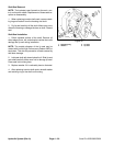
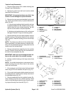
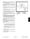
9. Position variable housing in a horizontal position.
Slide cylinder block assembly over the shaft engaging
splines. Make sure pistons and thrust plate remain in
place (Fig. 51).
10. Press needle bearing into the end cap. Bearing
must protrude 3/32 to 1/8 inch (2.38 to 3.18mm) from
face (Fig. 51).
11. Lubricate exposed face of the cylinder block with
clean hydraulic fluid (Fig. 51).
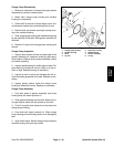
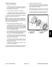
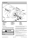
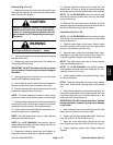
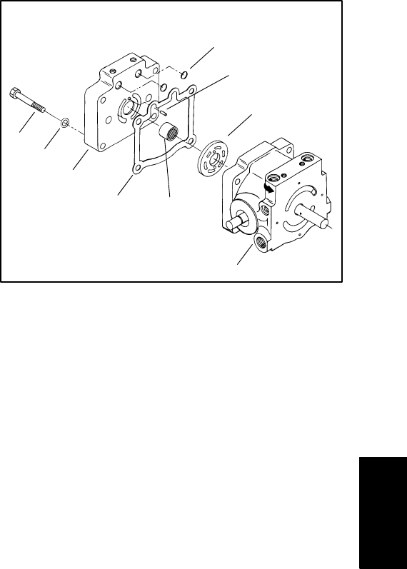
12. Position end cap to the variable housing. Lubricate
O–rings with clean hydraulic fluid. Position O–rings into
recessed holes of the end cap (Fig. 52).
13. Slide four cap screws through washers and end cap
holes. Place gasket onto the cap screws and the end
cap face (Fig. 52).
IMPORTANT: Make sure slotted and grooved side of
the valve plate is against the end cap face. The two
V–notches must face away from the end cap.
14. Insert locating pin into the end cap. Lubricate slotted
side of valve plate. Slip plate over pin and protruding
bearing (Fig. 52).
IMPORTANT: Make sure valve plate, gasket, and O–
rings stay in position when securing the end cap to
the variable housing.
15. Mate four cap screws to the variable housing (Fig.
52).
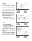
A. Tighten cap screws in an alternating pattern
while checking for proper assembly. Turn pump and
control shafts slowly while tightening cap screws.
B. Tighten screws until the housing and end cap are
completely pulled together.
C. Torque cap screws from 27 to 37 ft–lb (3.7 to 5.1
kg–m).
16. Assemble charge pump to variable housing (see
Charge Pump Assembly).
17. Install new lip seals to shaft and trunnion shafts (see
Shaft Seal Installation).
7
6
3
5
1
2
8
9
4
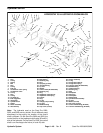
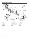
Figure 52
1. Cap screw (4 used)
6. Locating pin
2. Washer (4 used)
7. O–rings
3. End cap
8. End cap gasket
4. Variable housing
9. Needle bearing
5. Valve plate
Hydraulic
Systems
Sand Pro 2020/3020/5020 Page 4 – 55 Hydraulic System (Rev. A)