


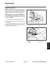
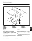
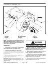
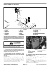

Front Wheel (SP 3020 and SP 5020)
FRONT
RIGHT
9
12
8
7
4
15
16
13
2
5
1
6
3
14
10
11
17
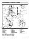
Figure 7
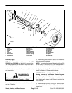
1. Set screw
7. Bearing tab
13. Spindle
2. Locking collar
8. Front fork
14. Bearing
3. Cap screw
9. Socket head screw
15. Lug nut
4. Lock nut
10. Lock nut
16. Drive stud
5. Relube flangette
11. Hydraulic motor
17. Wheel hub
6. Flangette
12. Front wheel
NOTE: The front wheel motors and wheels on the SP
3020 and SP 5020 are attached to the front fork in the
same manner. Therefore the same procedures can be
use for removal and installation.
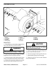
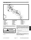
Removal (Fig. 7)
WARNING
Before jacking up the machine, review and follow
Jacking Instructions in Chapter 1 – Safety.
1. Park machine on a level surface, engage parking
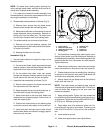
5. Jack up fork slowly until the hydraulic motor and
brake, lower attachment, and stop the engine.
flangettes can be removed from the fork. Remove flan-
gettes, spindle, wheel, and motor from the fork.
2. Loosen both set screws on the locking collar.
6. Slide flangettes and bearing assembly from the
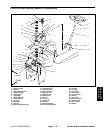
3. Support front of the machine. Remove three cap
spindle. Separate flangettes from the bearing.
screws and lock nuts securing the flangettes and bear-
ing tab to the fork.
7. Remove four lug nuts from the drive studs. Remove
wheel from the drive studs and spindle. Separate
4. Remove both socket head screws and lock nuts se-
spindle from drive studs and wheel hub.
curing the hydraulic motor the fork.
8. Secure hydraulic motor and hub to the machine to
IMPORTANT: Support wheel and motor when jack-
prevent damaging the hydraulic lines.
ing up the front fork to prevent dropping and dam -
aging the motor.
Wheels, Brakes, and Miscellaneous Page 6 – 8 Sand Pro 2020/3020/5020