


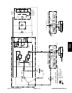
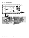
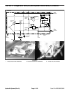
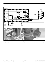
Procedure for Traction Pump Flow (P1)
(Fig.12):
1. Make sure hydraulic oil is at normal operating tem-
perature by operating the machine for approximately 10
minutes.
2. Make sure machine is parked on a level surface with
attachments removed. Make sure engine is off.
3. Read Precautions for Hydraulic Testing.
4. Make sure that traction pedal is adjusted to the neu-
tral and forward positions (see Adjust Traction Pedal for
Neutral and Forward).
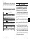
WARNING
Before jacking up the machine, review and follow
Jacking Instructions in Chapter 1 – Safety.
1. Jack up machine as follows to allow the drive
wheels to spin freely and to allow hydraulic flow through
the traction circuit:
A. On the SP 2020, jack up both rear wheels. Sup-
port machine with blocks or jack stands so that both
rear wheels are off the ground.
B. On the SP 3020 and SP 5020, jack up both rear
wheels and the front wheel. Support machine with
blocks or jack stands so that all three wheels are off
the ground.
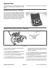
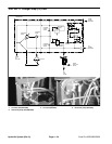
2. Disconnect hydraulic connections to install hydrau-
lic tester (flow meter).
A. On the SP 2020/3020, disconnect left hose at
the forward header.
B. On the SP 5020, disconnect bottom hose at the
front wheel motor.
3. Install hydraulic tester (flow meter). Make sure the
flow control valve is fully open.
A. On the SP 2020/3020, make sure the flow arrow
points out of the hydrostat and into the forward
header.
B. On the SP 5020, make sure the flow arrow points
from the hose and into the bottom port of the front
wheel motor.
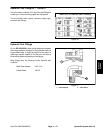
4. After installing hydraulic tester, start engine and run
at idle speed. Check for hydraulic leakage and correct
before proceeding with test.
5. Operate engine at full speed (3150 +
50 RPM).
CAUTION
Use extreme caution when taking gauge read-
ings. The tires off the ground will be spinning.
6. Slowly push traction pedal into the fully forward
position.
7. Slowly close flow control valve on tester until pres-
sure gauge on the hydraulic tester reads 1700 PSI. As
flow control valve is being closed, engine speed will de
-
crease to approximately 2200 RPM (verify engine
speed with a phototac).
8. Observe flow gauge. Tester reading should be mini-
mum flow of 7.5 GPM (28.4 LPM). Record test results.
9. Release traction pedal, open flow control valve on
tester, and turn off machine.
10. If 1700 PSI (tester pressure), 2200 RPM (engine
speed), or 7.5 GPM flow cannot be achieved, consider
the following:
A. The traction pedal and traction speed may need
adjustment (see Adjust Traction Pedal for Neutral
and Forward).
B. If the engine speed drops excessively (below
2200 RPM) as the traction pump load is applied, en
-
gine performance should be evaluated (see Chap-
ter 3 – Briggs & Stratton Vanguard Engines).
C. If engine speed does not drop and pressure and
flow specifications are not met, the hydrostat needs
to be repaired or replaced as necessary.
11. If specifications are met and traction circuit problem
exists, check wheel motor efficiency (see TEST NO. 4:
Wheel Motor Efficiency in this section).
12. If testing is complete, lower wheels to the ground.
Remove hydraulic tester and reconnect hydraulic hose.
13. Make sure hydraulic tank is full (see Check Hydrau-
lic System Fluid).
Hydraulic
Systems
Sand Pro 2020/3020/5020 Page 4 – 21 Hydraulic System (Rev. A)