


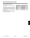
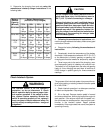

2. Determine the charging time and rate using the
manufacturer’s battery charger instructions or the
following table.
Battery
Battery Charge Level
Reserve
(Percent of Fully Charged)
Capacity
Capacity
(Minutes)
75% 50% 25% 0%
80 or less 3.8 hrs 7.5 hrs 11.3 hrs 15 hrs
@ @ @ @
3 amps 3 amps 3 amps 3 amps
81 to 125 5.3 hrs 10.5 hrs 15.8 hrs 21 hrs
@ @ @ @
4 amps 4 amps 4 amps 4 amps
126 to 5.5 hrs 11 hrs 16.5 hrs 22 hrs
170 @ @ @ @
5 amps 5 amps 5 amps 5 amps
171 to 5.8 hrs 11.5 hrs 17.3 hrs 23 hrs
250 @ @ @ @
6 amps 6 amps 6 amps 6 amps
above 6 hrs 12 hrs 18 hrs 24 hrs
250 @ @ @ @
10 amps 10 amps 10 amps 10 amps
CAUTION
60_F (15.5_
Charge the battery in a well–ventilated place to
dissipate gases produced from charging. These
Nausea may result if the gases are inhaled. Un-
plug the charger from the electrical outlet before
from the battery posts.
Do not charge a frozen battery because it can ex-
plode and cause injury. Let the battery warm to
C) before connecting to a charger.
gases are explosive; keep open flame and elec-
trical spark away from the battery. Do not smoke.
connecting or disconnecting the charger leads
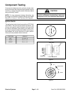
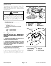
3. Following the manufacturer’s instructions, con-
nect the charger cables to the battery. Make sure a good
connection is made.
4. Charge the battery following the manufacturer’s
instructions.
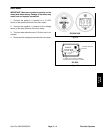
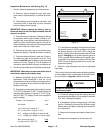
5. Occasionally check the temperature of the battery
electrolyte. If the temperature exceeds 125_F (51.6_C)
or the electrolyte is violently gassing or spewing, the
charging rate must be lowered or temporarily stopped.
6. Three hours prior to the end of the charging, mea-
sure the specific gravity of a battery cell once per hour.
The battery is fully charged when the cells are gassing
freely at a low charging rate and there is less than a
0.003 change in specific gravity for three consecutive
readings.
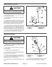
protection, so do not disconnect it. Check
lock system operation. If the switch is defec-
tive, replace it before operating. Whether the
not rely entirely on safety switches – use good
judgement!
WARNING
The interlock switch is for the operator’s
switch operation daily to assure proper inter-
switch is operating properly or not, replace it
every two years to assure maximum safety. Do
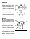
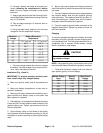
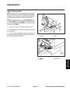
Check Interlock System
The purpose of the interlock system is to prevent the en-
gine from cranking or starting unless the traction pedal
is in “NEUTRAL”.
1. Check interlock operation in a wide open area free
of debris and bystanders. Stop engine.
2. Sit on the seat. Depress traction pedal in forward
and reverse directions, while trying to start the engine in
each position. If the engine cranks with the pedal in ei
-
ther the forward or reverse position, there may be a mal-
function in the interlock system. Repair problem
immediately. If the engine does not crank, the system is
operating correctly.
Electrical
Systems
Sand Pro 2020/3020/5020 Page 5 – 17 Electrical Systems