


22
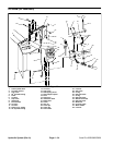
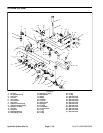
Hydrostat (SP 2020/3020)
27
28
30
15
2
4
5
6
7
12
14
15
16
17
18
20
21
23
24
25
26
8
9
10
11
13
3
3
16
17
18
19
19
20
31
32
29
33
34
29
FRONT
RIGHT
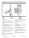
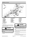
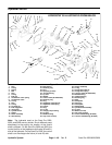
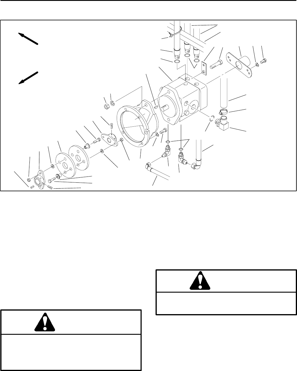
Figure 31
1. Not used 13. 90
o
hydraulic fitting
24. Pump hub
2. Shaft cover 14. Hydraulic hose
25. Pump mount
3. Lock washer 15. Cap screw
26. Woodruff key
4. Hydraulic hose 16. Lock nut
27. Hex nut
5. Hydraulic hose 17. Flat washer
28. Lock washer
6. Cap screw 18. Coupling spacer
29. O–ring
7. Wire standoff 19. Cap screw
30. Hose clamp
8. Suction hose 20. Set screw
31. O–ring
9. Hydrostat 21. Engine hub
32. O–ring
10. Push on hose fitting 22. Square key
33. Cable tie
11. Hydraulic hose 23. Rubber coupling
34. Hydraulic hose
12. 90
o
hydraulic fitting
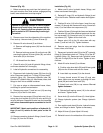
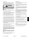
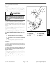
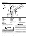
Removal (Fig. 31)
1. Before removing any parts from the hydraulic sys-
tem, park machine on a level surface, set brake, lower
attachment, and stop engine.
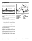
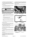
CAUTION
possible burns. Allow engine and exhaust sys-
The muffler and exhaust pipe may be hot. Avoid
tem to cool before working near the muffler.
CAUTION
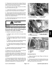
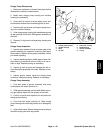
3. Remove muffler shield from the engine by first re-
moving three cap screws and lock washers securing the
Operate all hydraulic controls to relieve system
shield.
pressure and avoid injury from pressurized hy
-
draulic oil. Controls must be operated with the
4. Remove cotter pin and flat washer securing the
ignition switch in OFF. Remove key from the igni-
pump control rod to the pump lever. Pull control rod from
tion switch.
the pump lever (Fig. 32).
2. Pivot seat up. Remove cover from the midsection of
5. Label electrical wires. Disconnect wires from the
the machine.
neutral switch (Fig. 32).
6. Remove cap screw and lock nut securing the pump
lever to the hydrostat trunnion (Fig. 32).
Hydraulic System (Rev. A) Page 4 – 42 Sand Pro 2020/3020/5020