


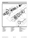
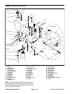
NOTE: The rotor set consists of the rotor (19), vanes
(20), and stator (21). Rotor set components may be
-
come disassembled during service procedures. Do not
service separately.
NOTE: It may be necessary to turn one alignment stud
out of the housing (3) temporarily to assemble rotor set
over the drive link (13).
NOTE: The rotor set rotor counterbore side must be
down against wear plate for drive link clearance and to
maintain the original rotor–drive link spline contact. A ro
-
tor set without a counterbore and that was not etched
before disassembly can be reinstalled using the drive
Figure 79
link spline pattern on the rotor splines if apparent, to de
-
termine which side was down. The rotor set seal ring
groove faces toward the wear plate (18).
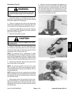
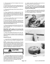
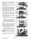
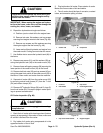
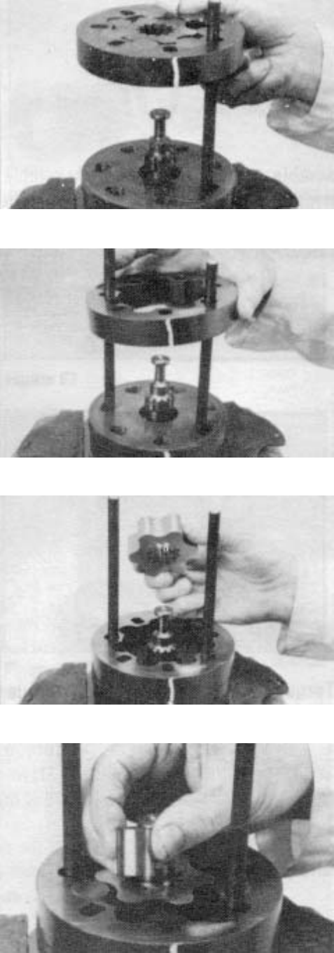
13. Install assembled rotor set onto wear plate (18) with
rotor (19) counterbore and seal ring side down. Splines
should mesh with the drive link (13) splines (Fig 79).
14. If disassembled rotor (19), stator (21), and vanes
(20) cannot be readily assembled by hand, assemble
with the following procedures:
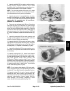
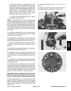
A. Place stator (21) onto wear plate (18) with seal
ring (5) side down. Be sure the seal ring is in place
(Fig. 80).
Figure 80
B. If assembly alignment studs are not being uti -
lized, align stator (21) bolt holes with wear plate (18)
and housing (3) bolt holes. Screw two cap screws
(14) finger tight into bolt holes approximately 180
degrees apart to retain stator and wear plate sta
-
tionary.
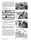
NOTE: If the manifold (22) side of the rotor (19) was
etched during wheel motor disassembly, this side
should be up. If the rotor is not etched and does not have
a counterbore, use the drive link spline contact pattern
apparent on the rotor splines to determine the rotor side
that must be against the wear plate.
Figure 81
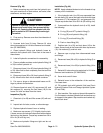
C. Place rotor (19) with counterbore down, if appli -
cable, into stator (21), and then onto wearplate (18)
so rotor splines mesh with drive link (13) splines
(Fig. 81).
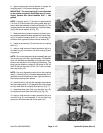
IMPORTANT: Do not force rotor vanes into place,
the coating applied to stator vane pockets could
shear off.
D. Assemble six vanes (20), or as many vanes that
will readily assemble into the stator vane pockets
(Fig. 82).
Figure 82
Hydraulic System (Rev. A) Page 4 – 68 Sand Pro 2020/3020/5020