


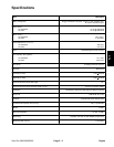
Throttle Control Installation
1. Secure throttle control to the dash panel or right
fender with both cap screws and lock nuts. Install throttle
control knob to the throttle control lever (Fig. 10).
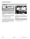
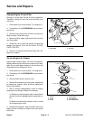
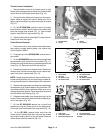
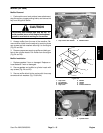
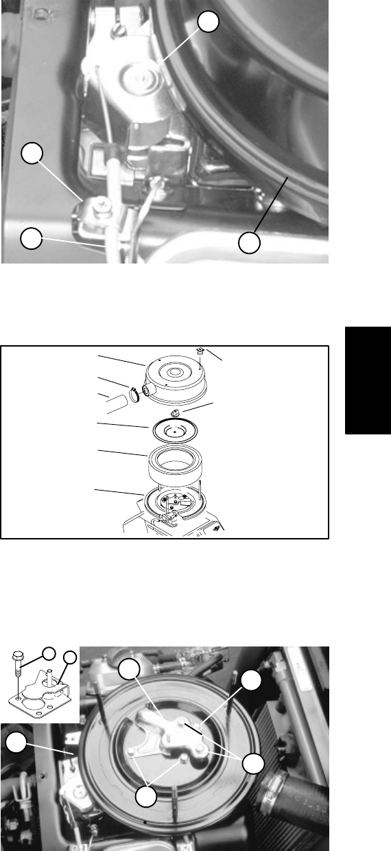
2. Connect throttle cable to the swivel on the engine.
Attach cable to engine with clamp. Make sure not to
tighten cap screw securing clamp and cable to engine
(Fig. 13).
3. On the SP 2020/3020, position hood to the dash
panel and front shield. Secure hood to front shield with
three hex flange head screws (Fig. 11). Secure dash
panel to hood with four cap screws (Fig. 12).
4. Adjust throttle control (see Adjust Throttle Control).
Install cover over the engine.
Choke Control Removal
1. Park machine on a level surface, lower attachment,
stop engine, engage parking brake, and remove key
from the ignition switch.
2. Pivot seat up. On the SP 2020/3020, remove the en-
gine shield.
3. On the SP 2020/3020 remove three hex flange head
screws securing the hood to the front shield (Fig. 11).
Remove four cap screws securing the dash panel to the
hood (Fig. 12). Remove hood from the machine.
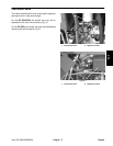
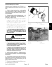
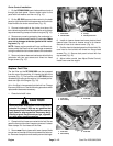
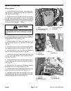
4. Remove air hose from air cleaner cover. Remove air
cleaner cover. Remove cover plate and air cleaner ele
-
ment from the air cleaner base (Fig. 14).
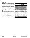
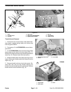
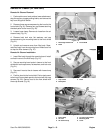
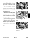
NOTE: Newer engine models will have a different car-
buretor shield that has five hex head flange screws se-
curing the shield and air cleaner base to the carburetor.
5. Remove two cap screws and three hex head flange
screws securing air cleaner base to the carburetor. Re
-
move base carefully from carburetor. Make sure not to
damage carburetor gasket. Cover carburetor to prevent
dirt and debris from entering (Fig. 15).
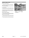
6. Release choke cable from clamp securing it to the
engine. Disconnect choke cable from the choke pivot le
-
ver on the engine (Fig. 16).
7. On the SP 2020/3020 remove hex nut and lock
washer securing the choke control to the dash panel.
Pull choke control and cable from dash panel (Fig. 10).
8. On the SP 5020, remove choke knob from the
choke control. Remove both lock nuts and cap screws
securing the choke control to the right fender. Remove
choke control from the machine (Fig. 10).
3
2
1
4
Figure 13
1. Throttle cable 3. Swivel
2. Clamp 4. Air cleaner
3
1
2
4
7
5
6
8
Figure 14
1. Hose clamp 5. Air cleaner knob
2. Air hose 6. Cover plate
3. Air cleaner cover 7. Air cleaner element
4. Air cleaner knob 8. Air cleaner base
1
3
3
2
4
3
5
Figure 15
1. Cap screw 4. Air cleaner base
2. Carburetor shield 5. Carburetor shield (newe
r
3. Hex head flange screw models)
Engine
Sand Pro 2020/3020/5020 Page 3 – 11 Engine