


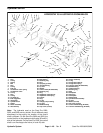
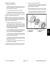
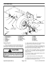
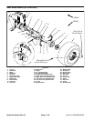
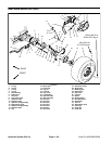
Front Wheel Motor
15
12
11
8
18
21
16
20
14
22
1
4
6
9
5
10
7
17
2
3
19
FRONT
RIGHT
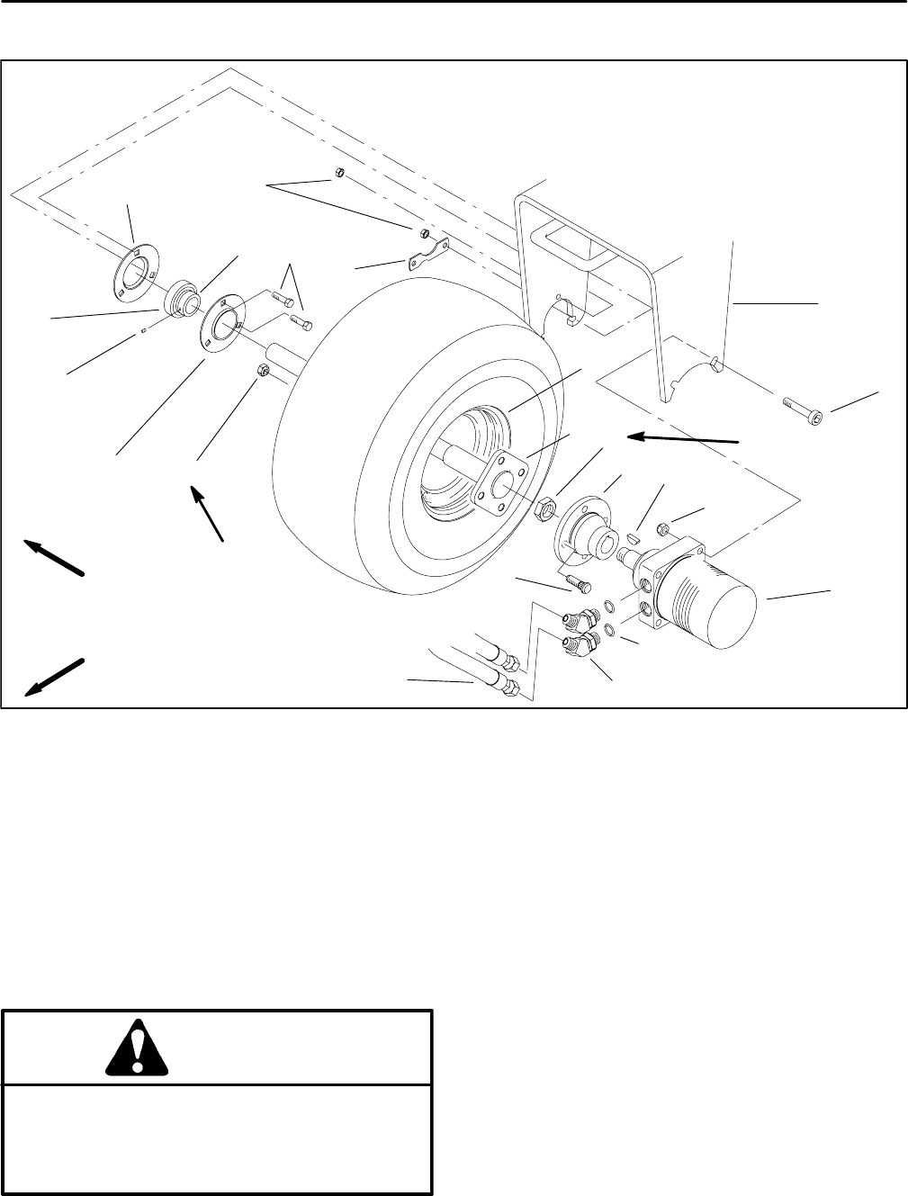
45 to 55 ft–lb
6.2 to 7.6 kg–m
200 to 400 ft–lb
27.7 to 55.3 kg–m
Figure 53
1. Hydraulic motor
9. Relube flangette
16. Spindle
2. 45
o
hydraulic fitting
10. Flangette
17. Bearing
3. Hydraulic hose
11. Bearing tab
18. Lug nut
4. O–ring
12. Front wheel fork
19. Drive stud
5. Set screw
13. Socket head screw
20. Wheel hub
6. Locking collar
14. Lock nut
7. Cap screw
15. Front wheel
8. Lock nut
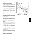
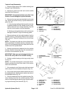
Removal (Fig. 29)
1. Before removing any parts from the hydraulic sys-
tem, park the machine on a level surface, engage the
parking brake, lower attachment, and stop the engine.
CAUTION
draulic oil. Controls must be operated with the
tion switch.
Operate all hydraulic controls to relieve system
pressure and avoid injury from pressurized hy-
ignition switch in OFF. Remove key from the igni-
21. Lock nut
22. Woodruff key
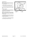
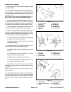
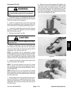
2. Clean hydraulic wheel motor, 45
o
hydraulic fittings,
and hydraulic hose connections thoroughly.
3. Label all hydraulic connections for reassembly. Dis-
connect hydraulic hoses from 45
o
hydraulic fittings. Al-
low hoses to drain into a suitable container.
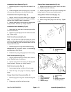
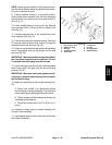
4. Match mark 45
o
hydraulic fittings and hydraulic
wheel motor for reassembly. Remove fittings and O–
rings from motor.
5. Put caps or plugs on disconnected hoses and fit-
tings to prevent contamination.
6. Loosen both set screws on the locking collar.
7. Remove three cap screws and lock nuts securing
the flangettes and bearing tab to the fork.
Hydraulic System (Rev. A) Page 4 – 56 Sand Pro 2020/3020/5020
13