


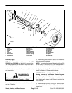
Sand Pro 2020/3020/5020Page 6 – 10Wheels, Brakes, and Miscellaneous
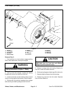
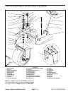
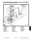
Rear Wheels and Brakes
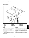
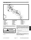
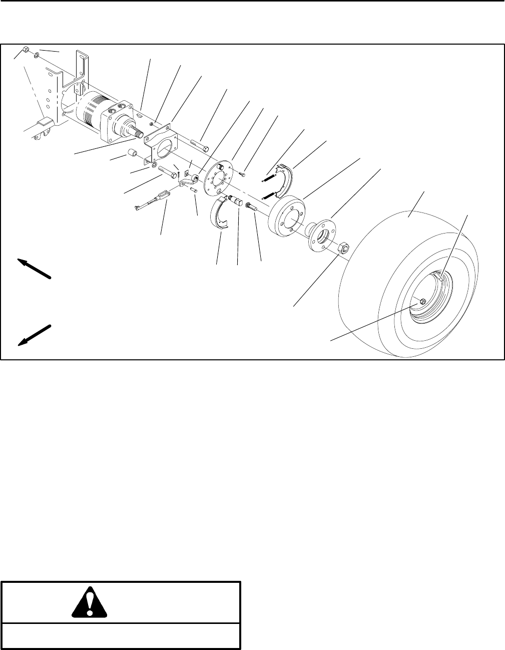
1. Lug nut
2. Drive stud
3. Wheel
4. Hub
5. Lock nut
6. Motor shaft
7. Brake drum
8. Woodruff key
9. Cotter pin
10. Clevis pin
11. Brake lever
12. Clevis
13. Backing plate
14. Retaining clip
15. Return spring
16. Brake shoe
17. Cam shaft
18. Brake bracket
19. Lock nut
20. Cap screw
21. Hex nut
22. Lock washer
23. Spacer
24. Cap screw
25. Valve stem
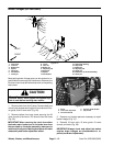
Figure 8
15
16
3
25
17
16
2
5
4
6
22
21
7
13
10
20
9
19
14
18
23
11
22
12
8
24
1
6
FRONT
RIGHT
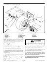
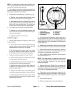
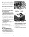
Removal (Fig. 8)
NOTE: The rear wheels and brakes on The SP
2020/3020 and SP 5020 are identical in construction.
The same procedures can be used for repair and main-
tenance of either machine.
1. Park machine on a level surface, lower attachment,
and stop engine.
WARNING
Before jacking up the machine, review and follow
Jacking Instructions in Chapter 1 – Safety.
2. Jack up rear wheel and use wood blocks to keep the
rear tire off the floor.
3. Remove lug nuts from drive studs. Pull wheel from
drive studs and wheel hub.
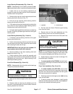
NOTE: The installation torque of the locknut is from 200
to 400 ft–lb (27.7 to 55.3 kg–cm). Use impact wrench to
remove lock nut from the hydraulic motor shaft.
4. Apply parking brake Remove lock nut from the hy-
draulic motor shaft. Release parking brake.
IMPORTANT: Do not hit wheel hub with a hammer
during removal or installation. Hammering may
cause damage to the hydraulic wheel motor.
5. Use puller to remove wheel hub and brake drum
from the hydraulic motor shaft. Remove woodruff key
from the shaft.
6. Remove cotter pin from clevis pin. Remove clevis
pin from brake lever and clevis. Separate clevis from
brake lever.