


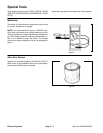
Component Testing
For accurate resistance and/or continuity checks, elec-
trically disconnect the component being tested from the
circuit (e.g. unplug the ignition switch connector before
doing a continuity check).
NOTE: For more component testing information, see
the Briggs and Stratton Vanguard Service and Repair
Manual for 4–Cycle, V–Twin Cylinder, OHV Engines.
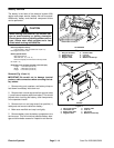
CAUTION
When testing electrical components for continu-
ity with a multimeter (ohms setting), make sure
that power to the circuit has been disconnected.
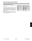
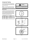
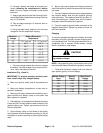
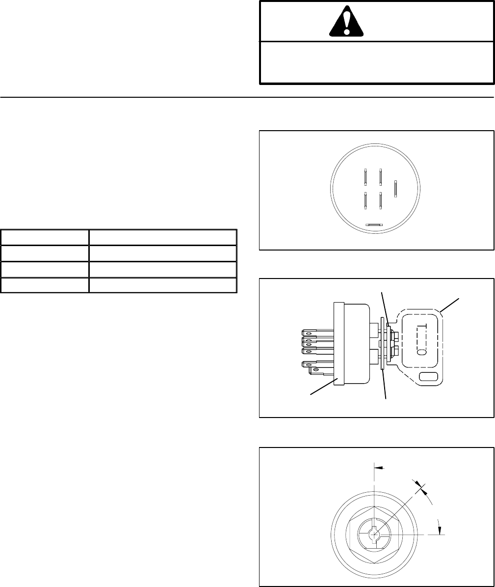
Ignition Switch
The ignition (key) switch has three positions (OFF, RUN,
and START). The terminals are marked as shown. The
circuitry of the ignition switch is shown in the chart. With
the use of a multimeter (ohms setting), the switch func
-
tions may be tested to determine whether continuity ex-
ists between the various terminals for each position.
Verify continuity between switch terminals.
POSITION
CIRCUIT
OFF G + M + A
RUN B + L + A
START B + L + S
G
L
B
S
M
A
Figure 3
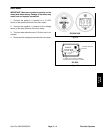
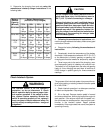
SWITCH
HEX NUT
KEY
LOCK WASHER
Figure 4
45 °
45 °
RUN/LIGHTS
OFF
START
Figure 5
Electrical Systems Page 5 – 10 Sand Pro 2020/3020/5020