


Lift Cylinder (SP 2020/3020)
Removal
6
1. Before removing any parts from the hydraulic sys-
tem, park the machine on a level surface, engage the
parking brake, lower attachment, and stop the engine.
1
2
6
5
8
3
6
6
4
4
1
7
CAUTION
draulic oil. Controls must be operated with the
tion switch.
Operate all hydraulic controls to relieve system
pressure and avoid injury from pressurized hy-
ignition switch in OFF. Remove key from the igni-
2. Label all hydraulic connections for reassembly.
3. Disconnect hydraulic hoses and O–rings from the
hydraulic fittings. Allow hoses to drain into a suitable
container.
4. Put caps or plugs on disconnected hoses and fit-
tings to prevent contamination.
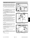
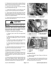
5. Remove cotter pin from the clevis pin. Pull clevis pin
from the hydraulic cylinder and lift arm.
6. Support hydraulic cylinder to prevent it from drop-
ping.
A. Remove a cotter pin from the cylinder pin.
B. Pull cylinder pin from the hydraulic cylinder and
frame.
C. Remove hydraulic cylinder from the frame.
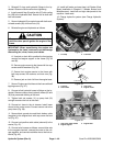
Installation
1. Position hydraulic cylinder tho the frame. Insert cyl-
inder pin through the frame bracket and cylinder. Secure
pin with cotter pins.
2. Position clevis of the hydraulic cylinder to the lift
arm. Insert clevis pin through the cylinder clevis and se
-
cure with cotter pins.
3. Remove caps or plugs from the disconnected hose
and fittings. Connect hydraulic hoses and O–rings to the
hydraulic fittings. Tighten hose connections.
4. Charge hydraulic system (see Charge Hydraulic
System).
Hydraulic
Systems
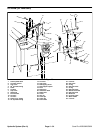
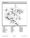
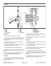
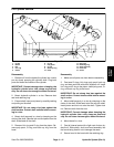
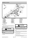
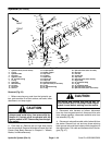
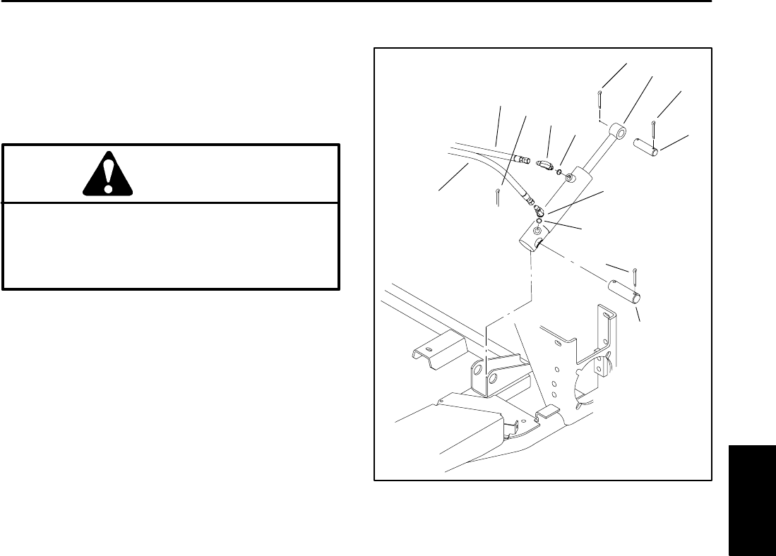
Figure 28
1. Hydraulic hose
5. Hydraulic cylinder
2. 90
o
Hydraulic fitting
6. Cotter pin
3. 45
o
Hydraulic fitting 7. Cylinder pin (clevis)
4. O–ring 8. Cylinder pin
Sand Pro 2020/3020/5020 Page 4 – 39 Hydraulic System (Rev. A)