


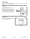
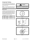
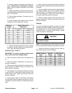


Starter Solenoid
NOTE: Prior to taking small resistance readings with a
digital multimeter, short the test leads together. The me
-
ter will display a small resistance value (usually 0.5
ohms or less). This resistance is due to the internal re
-
sistance of the meter and test leads. Subtract this value
from from the measured value of the component you are
testing.
1. Make sure engine is off. Disconnect solenoid elec-
trical connections.
2. Apply 12 VDC directly across the solenoid coil
posts. The solenoid should click. Make sure continuity
across the main contact posts is less than 1 ohm.
3. Remove voltage from solenoid coil posts. The sole-
noid should click. Make sure reading across the main
contact posts is infinity ohms.
4. Resistance across the solenoid coil posts should be
3.1 ohms.
5. Replace starter solenoid if necessary. Reconnect
electrical connections to solenoid.
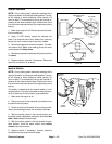
Figure 8
POSTS
SOLENOID COIL
POSTS
WIRING
DIAGRAM
SOLENOID COIL
POSTS
POSTS
SIDE VIEW
MAIN CONTACT
MAIN CONTACT
TOP VIEW
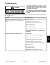
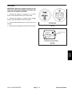
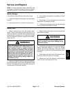
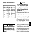
Neutral Switch
NOTE: Prior to taking small resistance readings with a
digital multimeter, short the test leads together. The me-
NEUTRAL
SWITCH
ter will display a small resistance value (usually 0.5
ohms or less). This resistance is due to the internal re
-
sistance of the meter and test leads. Subtract this value
from from the measured value of the component you are
testing.
This switch is closed when the traction pedal is in the
neutral position. The switch is located on the pump lever,
which is attached to the hydraulic pump assembly.
1. Make sure the engine is off.
2. Disconnect one of the electrical connections from
the switch terminal posts.
3. Check continuity of the switch by connecting a multi-
meter (ohms setting) across the connector terminals.
PUMP
LEVER
4. With the traction pedal in the neutral position and
Figure 9
the switch button depressed, resistance should be less
than 1 ohm between the terminals.
5. With the traction pedal in the the forward or back-
ward position, there the meter should read infinity
ohms across the terminals.
6. Replace switch if necessary. Connect electrical
connections to the switch terminal posts.
Electrical Systems Page 5 – 12 Sand Pro 2020/3020/5020